Understand check valves design features, specification and performance limits.
Self-study lesson plans and training record download page.
3 Tips for operating and maintaining check valves
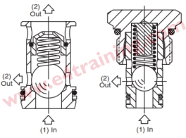
Check valves without springs should be fitted vertically such that gravity will close the valve, otherwise, they may not work.
In days gone by there was an old trick whereby, if a valve was not sealing, people would tap the ball or poppet with a hammer, to bed onto its seat. However, valves are made better these days and if it's leaking you've probably got some dirt on it. Hitting with a hammer is likely to wreck the seat with a dirt indentation. Remove the poppet, clean and replace. Check there are no wear marks around the seat contact area, particularly un-concentric ones. Remember the poppets will rotate around the seat.
Shuttle valves are commonly used to feedback load sensing signals back to the supply pump controller. On larger installations such as ships, a boost valve may be required to ensure the correct level of pressure signal is returned to the pump e.g. compensating for losses in the pilot return lines.
3-4 Design features and operating characteristics
If we look in detail at the design features inside a check valve we can understand exactly what affects their performance. We'll also find the same features in many other valves so you can easily use the same logic to predict the performance of similar valves as well.
Poppet nose effects on flow characteristic
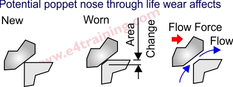 Check valves are made with a number of different poppet or ball designs. The shape of the nose and the type of material they are made of can have a significant effect on their performance and operating characteristic. For example the ball bearing design may be simple but it does not allow a good shape for limiting the flow forces on it. A soft seat, like all seats, will also distort such that it does not provide a sharp edge against the nose, but instead has a flat edge which produces a narrow passage for the flow to travel through. As the flow passes down this gap the fluid velocity increase and therefore the local pressure decreases (see Bernoulli effects) which create unwanted forces on the poppet and therefore distortions in the flow vs pressure characteristic.
The quality of nose design will have a significant effect on the quality of the flow characteristic.
Nose to bore concentricity effect on leakage
 The ball check valve is probably the most simple of hydraulic valves but also one of the most robust and reliable. The hardened ball is very accurately made and will form and settle into the hole to provide a good seal against the pressure, with no concentricity issues. The simple design means that, unlike poppets, which need a nose and spool body to be manufactured in exact concentricity, the balls have none of these complex concentricity's that can lead to an increase in leakage.
Leakage may not be critical for a back pressure generating check valve but certainly is for a load holding check valve. Accordingly there are lower cost valves where leakage is not so critical but if 100% leak free operation is important, then it's worth looking at the size/quality of the bore to nose design when you select which valve to use.
Contamination resistance factors
 If you do suffer with dirty fluid or aren't too worried about leakage then the simple ball design can be a great option. Apart from the risk of a soft seat being damaged from a collision with dirt, there are no spool elements where contamination can collect or stick.
All poppets are inherently resistant to dirt. If there is no leakage across the nose, then there are no forces trying to clog the valve. And even if the nose of a poppet does get blocked with contaminants, as soon as the valve opens the dirt is easily removed with the high local flows.
Of most concern for check valves, and when they are used as logic valves etc. are the spool section, in particular when they can have high pressure on one side and low pressure on the other side of the spool element. In these situations, the pressure difference across the spool will create leakage flow. This flow will draw contaminants into the gap between the bore and spool and if there is no significant flow around the end of the spool, the debris will not be cleared and could eventually cause the valve to stick and fail.
When specifying any spool element valve it is vital to consider where and when the high and low pressure will sit across the spool clearance and whether the flow can be used to clear the dirt. Remember that most failures are caused by contamination and high-pressure drop spools with limited flow are most likely to be where they will occur.
Manufacturing / design quality
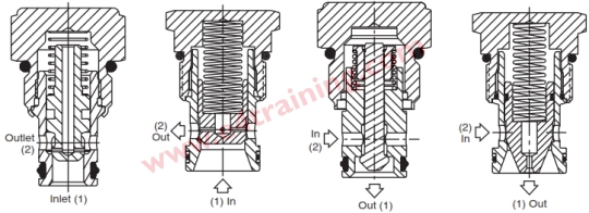
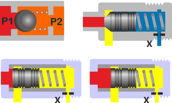 The way a valve is designed and manufactured will have a significant effect on its performance. Looking at these examples we can see that the ball bearing should be simple and reliable. The second (top-right) poppet should perform better but the seat will be soft as it is machined from the body. If it had a hardened seat pressed in then it might suffer from concentricity problems due to a build-up in tolerance errors. The bottom examples both have sleeves which should be harder materials with tighter tolerances and a concentric bore to nose.
Dynamic performance effects
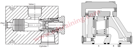 With many spool elements, there will be a trapped in volume of fluid connected to one end of the spool by a narrow pipe or orifice. This can be used to control the speed of response of the valve, depending on the galley way size or orifice.
Flow limits and pressure area
A check valve has two main functions. One to control the pressure at which point the valve opens (pressure area ratio and spring) and one to allow the flow through with as small a pressure drop as possible (galley way size). The PD (pressure drop) vs Flow is probably the most important factor when specifying a valve as users generally want to keep the energy or control loss to a minimum. The pressure area and spring size will affect this. The way the pressure changes when the valve opens is also critical as this will affect the flow/pressure characteristic and reset pressure.
3-4 How to specify check valve
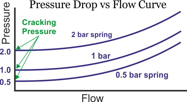
From a performance point of view, the first thing to consider is the maximum flow that will travel through the valve and the pressure drop you can allow at this flow. The second is the valve cracking pressure, ie the pressure at which it first opens. The graph shows several different valves of the same size but with different cracking pressures.
Although the function of check valves looks very simple. There are a wide range of different quality, performance and usage considerations.
In its simplest form, a check valve may just be a ball bearing against a round hole for a seat. The design is very cheap and robust but may leak later in life as the seat wears.
More expensive versions use machined poppets, hardened seats and spool bodies to ensure accurate location. Be careful to select the size and quality for your application taking into account the fluid contamination level expected, required life, and leak free performance. We say this because a ball and seat are very simple and robust. But as soon as you start adding spool elements you have additional spool clearances that may be prone to contamination. Also maintaining the spool bore to seat concentricity is particularly difficult so low leakage performance could be sensitive to quality issues, on less expensive valves.
4 Design Tips, techniques and potential issues
A common topic for lively discussions is whether any poppet valve, including check valves, can be leak free. It's certainly better to always expect a few drops per minute which usually means that your cylinder will drop after a few hours or overnight.
Of course, this is not always the case and if you have trapped in pressure you can guarantee that the valve will not leak a drop and a high daytime temperature change runs the risk of increasing the trapped in pressure to above the limits of your system.
Make sure you look at the manufacturer's datasheet for cracking pressure, reseat pressure and pressure rise rate against the flow.