Understand the different types of relief valve and when and where to specify them.
Self-study lesson plans and training record download page.
1-2 What pressure relief valves do and where they are used
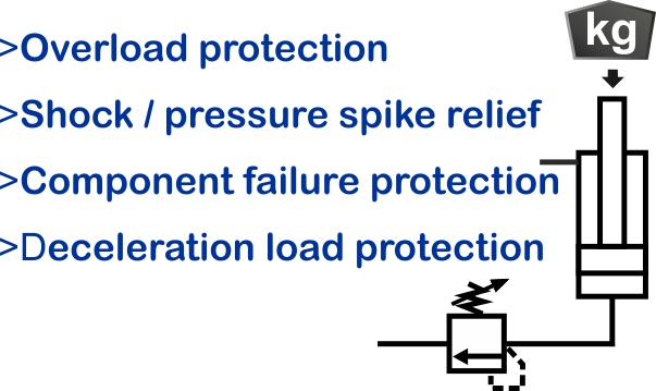
All hydraulic power supplies need to have a pressure relief valve somewhere in the circuit, to act as a safety protection device to stops the pressure from getting too high if something else in the circuit fails. A common location for these valves is directly after the pump.
Pressure relief valves can protect against high external loads acting on actuators that would increase the hydraulic pressure above the equipment's safe working limits.

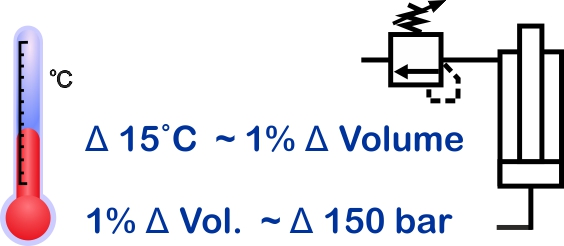 Where check valves are used in cylinder lines then pressure relief valves can protect against thermal expansion of the fluid, which can cause excessive pressures.
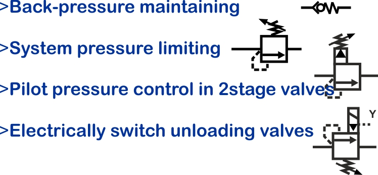 Pressure relief valves are occasionally used to control system or load pressure levels but because this generates heat and is an inefficient use of energy, they are far more commonly used as over-pressure protection devices.
One area where relief valves are used to control pressure levels is within pilot pressure control systems. Here the pilot flows across the relief valves are small but they act on other main spool or logic elements that control the main flow, without such inefficiency.
Another place where you may find a good quality relief valve is controlling the pressure on a test rig for example. Here it is acting as a convenient way to control the load pressure, but only for short periods.
By adding an electrical solenoid relief valves become electrical unloader valves e.g. as soon as the system registers a fault, or is turned off, the power is removed from the solenoid and the relief valve opens to ensure that no load pressure can be generated.
1-2 How pressure relief valves work

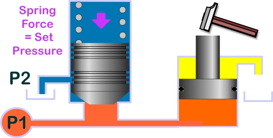
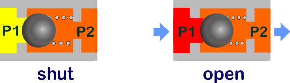
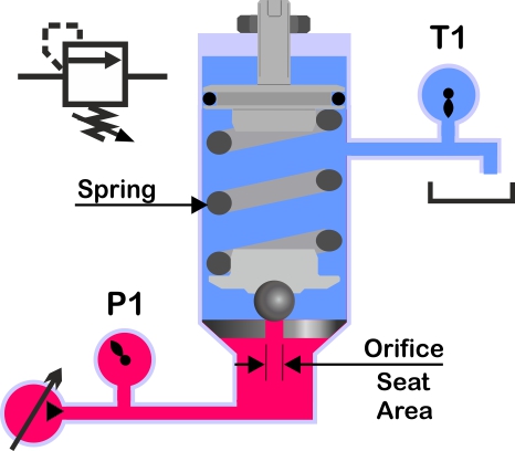
In their simplest form, a pressure relief valve can be a ball bearing held against an orifice by a spring. As the pressure increases on the ball seat area, the ball is pushed back against the setting of the spring.
Better quality valves will have hardened seats and shaped poppets to give better pressure vs flow characteristics and more consistent operation throughout their life.
Relief valves open when the pressure across them exceeds a pre-set limit. However, if the downstream pressure is acting on top of the valve poppet, (the end with the spring), then the actual pressure at which the relief valve opens will increase. Often multistage relief valves will have external pilot drains or feeds to ensure the control pressure level is stable and reliable.
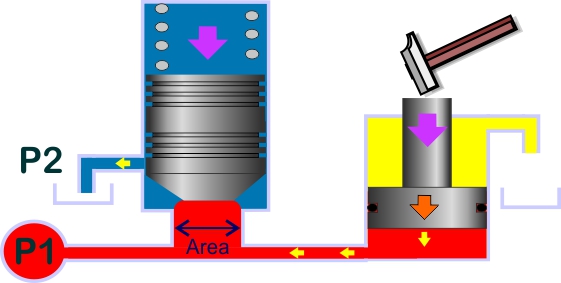
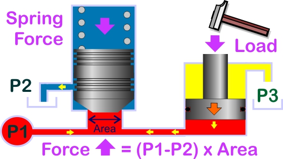 Excess load on the cylinder creates a pressure on the poppet nose, which forces the valve to open against the spring. The setting of the relief valve controls the maximum fluid pressure.
LOAD on cylinder creates PRESSURE
PRESSURE against poppet AREA creates FORCE
FORCE on spring creates MOVEMENT
MOVEMENT opens ORIFICE
 Under normal conditions, safety relief valves remain shut. The cracking pressure will equal the spring force or set pressure.
 The relief valve opens when the supply pressure exceeds the set pressure. As the flow increases the actual fluid pressure will also increase slightly. Valves also reseat at a slightly higher pressure than they first open. Circuit designers often leave a 15 bar minimum clearance between different pressure control devices.
High flow valves tend to have two stages with a small pilot relief valve that opens a larger, second, main stage valve.
2-3 Different types of pressure relief valve
See also pressure control valve in our symbols sections for more details.
All relief valves are not the same. Simple ball and spring valves are cheap to produce but will not have such a good operating characteristic as to ones where the manufacturer has developed a carefully shaped poppet nose. This may not be a problem if it's purely a safety relief valve that should never operate, however, controlling the pressure against different flow rates on a test rig will require a much better standard of valve.
Relief valves options include direct-acting, pilot operated 2-stage, electrical unload, electrical proportional, integrated or line mounted versions.
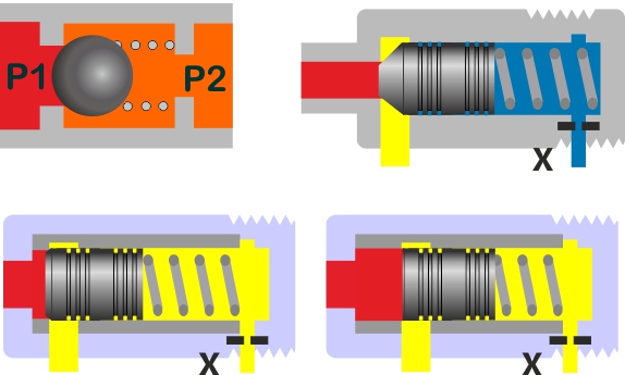
Figure 1 shows a simple ball valve; a basic poppet operating against a soft seat in the valve body; a quality poppet with a hard seat in a concentric sleeve; and just a spool in a sleeve with no poppet seat. Typically harder seats and more accurately machined sleeves give longer life, better and consistent characteristics, along with better reliability.
Bypass relief and back-pressure maintaining valves
Check valves can be used to provide a simple type of relief valve. These are commonly used as bypass pressure relief valves or backpressure maintaining valves. The spring size vs area ratio restricts check valves to only low pressures. Back-pressure maintaining valves are used when it's beneficial to maintain a small pressure in certain areas of the circuit.
Direct operated relief valve shut
By adjusting the compression of the spring that acts directly on the ball valve, we can control the pressure at which the relief valves open. The spring size in a direct operated valve is large compared to the orifice area. This limits the maximum flow area and therefore flow capacity of the valve.
Direct operated relief valve open
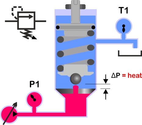
With only a few simple components, direct-operated relief valves respond quickly and can be robust and reliable. When relief valves open, all of the energy that is dissipated through the pressure loss is converted to heat and taken back to the reservoir within the fluid.
Differential area relief valves
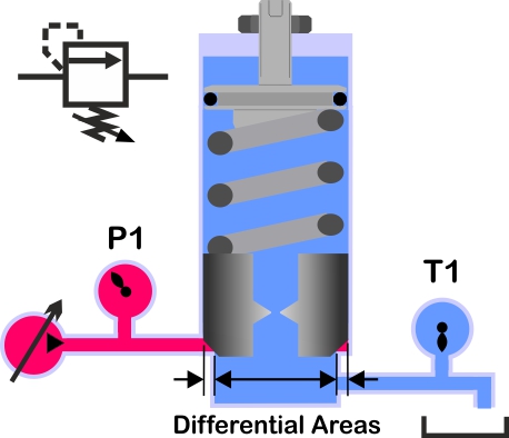
Differential area valves have similar performance to standard direct operated valves but have larger flow paths. The concern with differential area valves is that their spool clearances increase the risk of failures due to contamination.
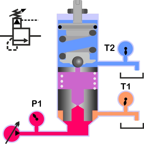
2-Stage, pilot operated relief valves
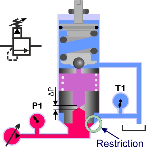
Direct operated relief valves are used as pilot pressure control valves to open larger spools or poppets and therefore control larger flow rates. As the pilot valve opens it creates a flow across the orifice in the middle of the main spool valve. The flow creates a pressure difference across the spool and the corresponding force opens the restriction at the valve seat. As the line pressure continues to rise, the spool PD increases and the more the valve opens to discharge more fluid. The pilot pressure can also be sensed remotely, from somewhere else in the circuit.
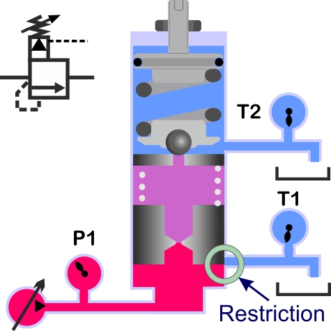
2-Stage, pilot operated relief valve with external drain
Keeping the pilot drain line T2 separate will maintain a more stable operating pressure by referencing the set pressure to tank. 2 Stage valves can include an extra remote pilot drain line T2 to ensure the operating pressure is always referenced back to a stable tank pressure. The main return flow line T1 is likely to suffer from pressure surges as other valves open and without a separate pilot line, these oscillations will also be seen upstream of the valve.
Spool or poppet main-stage valves
The main stage valve restriction may utilise a spool control land or a poppet seat. It is important to know exactly how each valve works as the performance of a spool or poppet control land will be significantly different. A spool is likely to give better control but exhibit higher leakage and be more sensitive to contamination.
Poppet shape affects the flow forces and performance curves
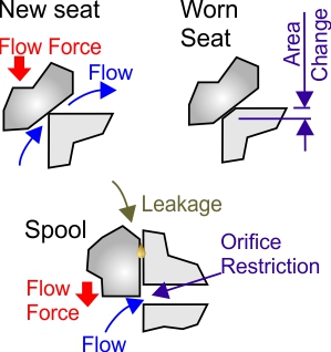
The detail design of the poppet seat or spool opening will affect the flow forces acting on the valve and therefore how flat its performance characteristic will be. Valve costs vary considerably and the reason for this is usually that to ensure the best operating characteristic and service life then better materials and more sophisticated manufacturing techniques are required.
Relief valves in accumulator safety blocks must be certified and sealed. These are different to normal relief valves because accumulators fall under the PED (Pressure Equipment Directive). You must not reset or replace these valves with non-certified components.
Advanced relief valve training
Learn more about relief valves in our 'Professional Training Section'. Understand their design features, performance limits, and how to specify relief valves.