Self-study lesson plans and training record download page.
Learn about the key performance and reliability issues
This section highlights the key performance and reliability issues within a typical mobile hydraulic system. If you need to maintain hydraulic equipment or diagnose faults then probably the most important skill is understanding, and being able to identify, the key risk points and typical issues. The main areas are as follows:
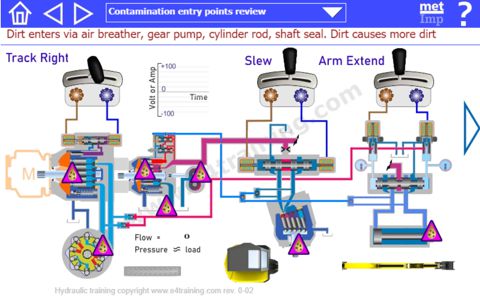
Contamination entry points
Contamination cause 80% of all failures. Microscopic particles of dirt get into the hydraulic fluid and flow around the circuit, blocking spool clearances and stopping valves from operating. Over long periods they will gradually wear sliding surfaces creating higher leakages and lower performance efficiencies.
Every effort must be made to ensure that contamination cannot enter the fluid. The following are some of the key risk points although more details can be found in our contamination section HP04.
Dirt entry points include the air breather, gear pump, cylinder rod, shaft seals. Once contamination is in the fluid then piston pumps can create even more dirt.
Potential contamination failure points
Micronic dirt particles hold poppets valves open and block the gaps in spool valves to stops them moving smoothly. Every valve is susceptible to failure and every pump or motor susceptible to wear. If a function is not working and the electrical drive signal is OK; then it's probably contamination causing intermittent valve operation or total failure. To identify the components that are likely to fail first, or most often, look for spools that have low control pressures driving them or high-pressure drops across their control lands.
Spool leakage or flow loss points:
Hydraulic components take huge loads for long durations because no metal components touch each other. They are separated by fine clearances or fluid bearings that keep the surfaces apart. However, this means there will be some leakage from most components.
When testing hydraulic equipment it is generally very difficult to the mainline flow rates as they tend to be high flows at high pressure. Also, it can be difficult to identify any useful results. For example, if a pump is starting to fail and the internal leakage increases by a massive 100% e.g. from 1 to 2 L/min, this would hardly show in the main flow 200 to 199 L/min. Easily within normal gauge reading errors. So we can see that monitoring pump case leakage flow will give a much clearer indication for when the pump is starting to fail. Spool and pilot leakages can also have a much more significant effect on back pressures in drain lines, which again can have a more significant effect on pump life or valve control accuracy.
Increases in case or pilot drain flows can sometimes be identified by simply feeling for warmer pipes.
Heat sources due to high pressure drops
Fluid power uses the energy dissipated in pressure drops to control flow rates or services. These energy losses create local hot spots in the valves and pipework, which is quite normal and provides an easy way of identifying what parts of the circuit are working hardest. Ofcourse, if we are not using parts of the system but they are still showing as hot, then perhaps we have identified a potential issue. Or if they are not hot when they should be.
As with many hydraulic testing stratagies, it is vital that technicians have a data recorded from when the equipment is working well, so that they can compare this with when there is a fault.
Fluid power risk points
Fluid power equipment controls movement, so can be very dangerous. It is vital that personnel are kept at a safe distance from moving equipment. Startup and shutdown can be particularly dangerous as uncontrolled or unexpected movements can occur. It is also important to always leave the equipment in a safe condition when the vehicle is turned off. Actuators will creep when stationary if they are not left in a safe, supported, position.
Particular risk points include lowering or slowly dropping loads, uncontrolled slew movements due to gravity on slopes, brake or flexible hose failures.
Air ingress points
Air pockets inside the hydraulic system can cause intermittent or spongy operation. A properly filled reservoir is important for allowing air bubbles to be released safely.
Under most circumstances the fluid pressure is always above the external air pressure, so no air will enter the system. However, pump suction lines may operate below ambient pressure so can draw air into the fluid, if there is an air leak in the suction line. Cylinders can also generate negative pressures if the actuators are left unsupported and may then draw air in past the rod seals.
Hydrostatic drive circuit maintenance
This section looks at the maintenance tasks you might need for a typical hydrostatic drive system. For more general and detailed maintenance information refer to our maintenance section.
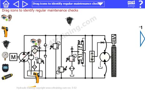
Typical daily maintenance checks
The following is a typical list of components that can be easily inspected each day before the vehicle is started.
- Check hydraulic fluid level is within limits and look for leaks at pipework fittings.
- Check all functions work with normal operating power and speeds
- Inspect for damage to drives, cylinders, rods, pipework, electrical equipment or mechanisms
- Check hydraulic hose condition for wear, cracks or leaks
- Check filter clogging indicator while running and at startup
- Keep cylinder grease points lubricated with a greasing gun, as required
- Check coolers are free from debris and dirt which could cause overheating
- Check Air breather is clear of debris and element is clean
Planned maintenance checks
The following is a typical list of components that might be included in regular maintenance checks. In practice, maintenance technicians should follow the vehicle-specific maintenance procedure documents along with any service history details.
- Regular fluid contamination sampling
- Replace hoses, fluid and air filters in line with vehicle usage replacement schedule
- Record tank and case drain temperatures under standard test conditions
- Time standard operations as an invasive way of checking the pump flow and internal leakages
- Check key pressure settings where gauges are fitted or test points are available. Fit test points if required.
Typical hydrostatic drive specific maintenance tasks
The following table outlines examples of some typical maintenance work that might need to be carried out on a hydrostatic drive system.
| Component | Daily maintenance | Planned maintenance | Component maintenance instructions |
|---|---|---|---|
| Piston pump | None | Record case drain temperature under standards test | Keep fluid in good condition to avoid high pump maintenance. Increasing case drain flow/temperature are early warning signs. Look and listen for unusual noises, slow or erratic operation. Plot pump PQ curve to check, always replace before it fails to avoid debris. Rotary group and swashplate are replaceable. |
| LSHT Motor | Watch for slow speed or poor performance | Time check for slow speed or poor performance. Record case drain temperature. | Listen, measure case leakage line temperature and flow. Time the vehicle speed operation under load although changes in reservoir operating temperatures a more likely guide to trouble. |
| Gear pump | None | None | Listen, check temperature, and look in filter for debris as early sign of failure, check suction for restrictions or air leaks. Plot PQ curve to check. Replace only. |
| Flexible Hoses | Visually inspect for wear, damage or leakage | Inspect for wear, damage, leakage and replacement date | Visually inspect for damage or wear, replacement due date, guarding against whip injury, temperature rating for operating restrictions. |
| Fluid filter | Visually check clogging indicator level | Watch clogging indicator and replacement date | Observe clogging indicator at startup (cold) and operating temperature (hot). Check date of last change. Record fluid contamination level. Inspect debris for signs of pump failure. |
| Air breather | Visually check for blockages | Visually inspect, replace to schedule or before | Visually inspect condition. Check last change date and appropriate rating for environment. Change based on visual checks or air pressure in reservoir which will affect pilots and return line pressures. |
| Relief valve | None | Check setting if test point available | Temperature check will indicate if open. Check pressure settings at test point and flushing relief set high. Turn vehicle off to adjust or set on deadweight tester. |
| Check valves | None | None | If the vehicle freewheels then check valves may be leaking. Check charge pump working pressure as guide to issues. |
| Relief valve | None | Check setting if test point available | Remove to test on deadweight tester. Scale via nut rotation only if absolutely necessary. Valve should remain shut and leak-free all of the time. |
| Relief valve | None | Check setting if test point available | Remove to test on deadweight tester. Scale via nut rotation only if absolutely necessary. Valve should remain shut and leak-free all of the time. |
| Directional valve | None | None | Check pressure at outlet. Measure outlet flow from valve. Observe temperatures |
| Shuttle valve | None | None | Observe cylinder movement. Check line pressure. Time cylinder movement |
| Relief valve | None | Check setting if test point available | Temperature can indicate when open. Turn vehicle off to adjust or set on deadweight tester. |
| Cooler | Visually check for debris restrictions | Visually check for debris and clean | Reservoir temperature should remain stable. Measure temperatures before and after. Compare reservoir and line temperatures. |
| Fluid reservoir | Visually check fluid level and leakage at pipe fittings etc | Check fluid and contamination levels. Record temperature | The reservoir is key to keeping the fluid in good condition. Check fluid level, contamination, temperature, aeration, and fluid quality analysis. Use external filter unit to clean fluid. |
Typical hydrostatic drive specific commissioning
When a hydraulic system is first built or new components are fitted or repaired, then a process of commission might be required to ensure everything is working appropriately for the vehicle to be returned to service. This would mainly involve flushing the fluid and pipework to the required cleanliness level, however, the following table includes some typical commissioning work that might need to be carried out on a hydrostatic drive system.
| Component | Description |
|---|---|
| Piston pump | Flush system until clean, inspect for leaks, record measurement data. Case drain and suction pressures critical. |
| LSHT Motor | Replace the motor with a flushing, flow, and pressure measurement device. |
| Gear pump | Listen, check suction head and air leaks |
| Flexible Hoses | Visually inspect for damage or wear, manufacture date, guarding, temperatures for restrictions. Keep a hose register for replacement dates. |
| Fluid filter | Observe clogging indicator with fluid hot and cold. Check date of last change. Record fluid contamination level |
| Air breather | Replace regularly depending on condition and environment. |
| Relief valve | Set as cracking pressure using deadweight tester before assembly |
| Check valves | Compare forward and reverse speeds |
| Relief valve | Set as cracking pressure using deadweight tester before assembly. |
| Relief valve | Set as cracking pressure using deadweight tester before assembly. |
| Directional valve | Confirm circuit operation including relief and cooler function. |
| Shuttle valve | Confirm brake operation and release before leaving the workshop. |
| Relief valve | Set as working pressure while operating. Only adjust when machines is turned off. |
| Cooler | Measure temperatures of pipework and confirm stable reservoir temperature control before leaving workshop. |
| Fluid reservoir | Check fluid level with cylinders extended and retracted. Measure contamination level. Check aeration, temperature, fluid quality analysis. |
How to diagnose hydraulic equipment faults
There is no substitute for detail knowledge of each component and the fundamental hydraulic principles involved, however, common sense and a systematic approach to fault finding are also valuable tools.
There is additional information about troubleshooting procedures here although techniques may typically include:
- Quantifying how the system has changed compared to normal operation.
- Researching vehicle documentation to see recent operating duties and service history.
- Gathering all relevant design drawings, component data, and records of similar issues.
- Measure the operating parameters and compare them with normal operating performance data.
- Run tests to identify possible causes. This may involve swapping or removing components for independent checking on a test rig.