Self-study lesson plans and training record download page.
Industrial power unit design project
This project will guide you through some of the key design features in a hydraulic power unit. We cover the operation, components, maintenance and testing. Exercises require students to diagnose and repair typical faults.
The simulation also reviews a range of calculations required to design a hydraulic reservoir. It is based on an industrial power unit although the same calculations will apply to mobile power units etc. The key difference between them is the cost and weight, with mobile units working with significantly smaller reservoir and pipework sizes.
The size of the power unit will depend on the loads but we discuss these in other articles.
Hydraulic power unit and control valve test rig
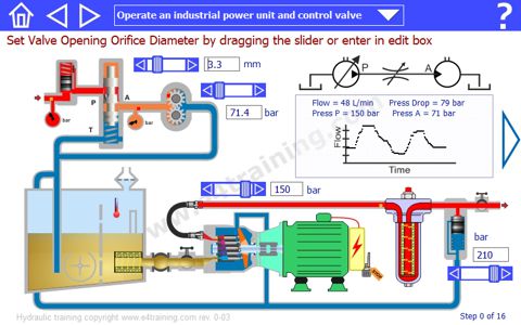
Operate an industrial power unit and control valve. Change the pressure and flow control settings within the power unit to observe how the performance changes and the different parameters affect each other. Click and drag the slide bars to change each valve's setting.
Learn the main components in a typical hydraulic system. Move the mouse over each component to find out what it is and what it does.
Build a hydraulic power unit. Drag and drop the components to move them into their correct location.
Identify all pressure control valves by dragging the pressure symbol over the correct parts.
Identify all flow control valves by dragging the pressure symbol over the correct parts.
Identify all air and fluid filters by dragging the pressure symbol over the correct parts.
Learn how to maintain equipment by monitoring the key parameters and following the required procedures.
Learn about suitable test methods, typical faults and repair methods for hydraulic equipment.
Exercise 1 is to find the correct orifice size to give a specific flow rate at a given load pressure.
Exercise 2 is to diagnose what is wrong with this circuit. There is a built-in fault which students have to find and repair.
Exercise 3 is to diagnose an urgent maintenance requirement that students have to identify and repair.
Exercise 4 is to diagnose a component that is starting to fail. Students must identify the signs and then repair.
Reservoir volume calculation
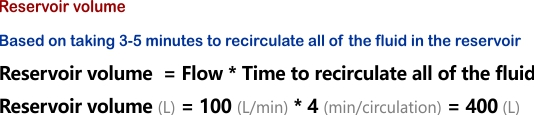
The ideal reservoir volume is generally quoted as between three to five times the flow per minute. This means that the complete volume of the tank circulates through the system ever 3 to 5 minutes.
In reality, the optimum size depends on many factors and can be critical for trouble-free running. These are just some of the issues it will affect: contamination levels due to filter passes and dirt settling, system temperatures, aeration of fluid, fluid quality, pump inlet pressures, pilot line pressure stability.
With mobile equipment, there are real benefits from keeping the reservoir as small as possible but this is only possible with significant experience and development work to establish the smallest possible size in each application.
Reservoir design for good pump inlet conditions
Maintaining good pump inlet conditions is vital for achieving a long pump service life. There are five key factors that will affect this.
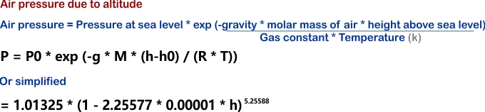
1. Local air pressure will vary depending on how high the unit is above sea level. It's the air pressure that pushes the fluid into the pump so this needs to be taken into consideration when working much above sea level.
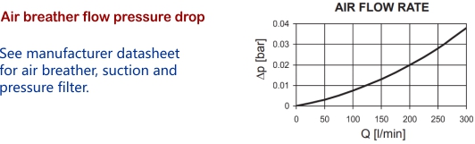
2. Air filter pressure drop . As the cylinders extend, fluid is taken from the reservoirs and air is drawn in. As the air passes through the air breather there will be a pressure drop created across it. If the filter becomes clogged with dirt then the pressure loss can be high enough to damage the pump.
Air filter pressure drops are worked out by checking the manufacturer graphs of pressure drop against flow provided in the component datasheets.
3. Fluid pressure heads have a significant effect on pump inlet pressure. A positive pressure head will improve the pump inlet although if the pump is located above the fluid then the pump will have to draw the fluid up and is more at risk of damage.
The pressure head calculation is relatively easy and is either added or subtracted from the total inlet pressure head.
4. If suction filters are used then their pressure drop must also be considered in the same way the air filter is e.g. by looking at the manufacturer datasheet.
5. All pipework will create a pressure drop across them. Pump inlet lines are generally very short with a large diameter but it's always worth checking their effect, particularly at low temperature, start-up conditions when appropriate.
Pipework pressure loss calculations
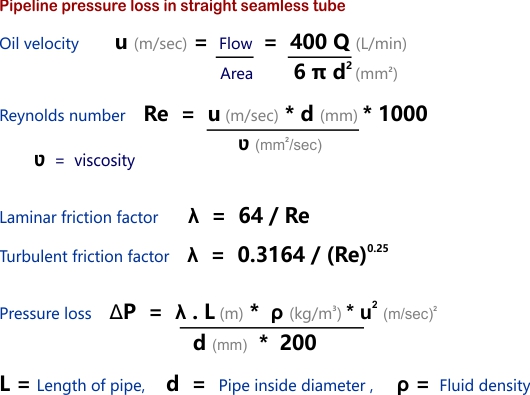
As fluid moves along a pipe there will be a small pressure drop due to friction between the fluid and the pipe wall. The friction will be different with turbulent or laminar flow which is assumed to change when the Reynolds number is around 2300.