Self-study lesson plans and training record download page.
What gear pumps and motors are used for
External gear pumps are generally fairly robust, high-pressure devices. They are low cost and will work with higher levels of contamination which means they are popular mobile applications. Unfortunately, they do also generate dirt so don't tend to be so widely used in industrial systems and are definitely not suitable for high-performance systems.
Typically operating conditions up to 250 bar and 100cc/rev with 1000hrs full load life.
Gear pumps are far more commonly used than gear motors. Typically low cost mobile power units or low pressure lubrications systems.
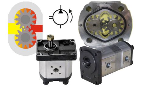
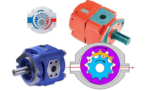
How hydraulic gear pumps and motors work
The gears rotate inside the body carrying fluid around the outside of the gears. The fluid cannot return through the centre of the meshing gears so is forced out through the pressure port.
In the majority of external gear pumps the gear and bearing assembly float within the body which allows the gear tips to 'cut in' and provide very tight tolerance and therefore low leakage past the gear tips. The side bearings are pressurised against the gear side faces maintaining a minimum leakage rate.
Gear motors require and extra case leakage line to prevent the higher return line pressure damaging the shaft seal.
Different types of gear pumps and motors
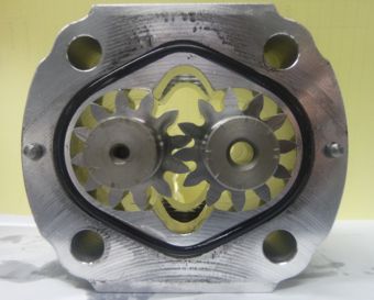
There are two main types of gear pump and motor. The floating bearing pack design and a fixed bearing design.
In the floating bearing pack design, the drive and driven gear are assembled inside the bearing blocks and float slightly within the body cavity. With high pressure on one side of the gears, the floating gear and bearing assembly are forced back against the inlet side of the pump body, therefore, giving very low clearance between the rotating gears and the pump body; this helps give the high volumetric efficiency of the design. In fact, during the manufacture of these pumps, they are run at their maximum pressure in a controlled manner and the gears cut themselves into the body to produce the finest clearance tolerances. For this reason, gear pumps should not be subjected to any pressures higher than their rated pressures as they will then cut further into their bodies creating damaging contamination and reducing efficiency.
Seals within the ends of the floating bearings are shaped to push the bearings against the side of the gear faces thus reducing clearances and increasing efficiency.
Tandem or multiple gear pumps can be driven from one drive by piggy backing the drive gear of all the pumps.
Tips for operating and maintaining
A key installation issue with the floating bearing gear pump design is their dislike of side loads on the drive shaft. Internal forces are so high that the pumps can work perfectly if simply suspended from their own drive shaft, however, if they are driven without a flexible coupling or by belts or gears that apply side loads, their efficiency may be severely affected.
Good suction ability but always avoid running dry or drawing fluid above the manufacturers specified pressure head. Although they will self-prime, this is likely to severely reduce the operating life.
Mechanical and volumetric efficiency will always be limited by the gear tip and side sealing face leakage. Be aware that these can change with operating temperatures outside of their normal working range.
Be very careful never to overpressurise a gear pump or motor above its rated pressures. Because the gear tips cut into the body during the manufacturer's final production testing, if you then apply a higher pressure the teeth will cut in even further, sending high levels of dirt into your hydraulic system.
Typical operating characteristic
Consult the manufacturer's datasheet for specific operating conditions although be aware that data for low temperatures or different fluid viscosities is not normally provided. At low temperatures, during cold start it's quick likely the 90% efficiency quote will fall below 50%.
How to specify gear pumps
Pumps perform well across a range of operating conditions although efficiencies will vary with speed, pressure, and temperature, which may be a problem the input power is designed for optimal working conditions.
Try to avoid steep pressure rise rates, which can also reduce working life. See the manufacturer's working pressure peak curves in their datasheets.
Watch for side loads on drive shaft e.g. avoid belt or helical gear drives.
Use super finished bearing for higher duty applications.
Noise
It's now common for gear pumps to have a 12 tooth design as this is generally quieter than 9 teeth. The amplitude of the pump ripple is dependent on the number of teeth on each gear. More teeth will give more ripples of lower amplitude. Depending on the resonant frequency of the machine this will generally reduce the noise level generated by the equipment, although it will be at a higher and possibly more annoying frequency.
The quality of gear teeth form can also affect the noise levels between pumps. Gears shapes are designed for constant speed transmission drives but in gear pumps, this is not important so the form shape can be modified to vary the speed of the second gear and therefore balance out the uneven flow ripple. Machining errors make it worse.
Quite gear pump designs are now available using either:
1. Form modification (to anti-phase driven gear to compensate for fluid pulses)
2. Zero backlash (making a 12 tooth pump equivalent to 24 teeth)
3. Helical gear (reduces fluid pulsations)
4. Anti-phase compensator (tiny pump just to provide negative of noise signal)
All of the above are however likely to have a small negative effect on mechanical and/or volumetric efficiency.
Design Tips, techniques, and potential issues
In the fixed bearing design, the gears do not float but rely on tight manufacturing tolerances to maintain fine clearance between the gear tips and the pump body. The fixed bearing designs tend to be more expensive than the floating bearing design, but still a lot less than piston pumps. Fixed bearing designs tend to have larger displacements and are more commonly used for supplying large flow at low pressure e.g. for off-line coolers/ filter units.
Tandem pumps
Multiple gear pumps can be driven from one drive by piggybacking the drive gear shaft through to all of the pumps. Beware of designs that drive the second pump from the driven shaft of the first pump. Gear pump gears are not designed with the same parameters that transmission gears are and therefore aren't good at transmitting power through their gears.
Internal gear pumps
Many details are similar to the external gear pump details above.
This design does have more mechanical sealing faces that would normally result in increased losses however, the products tend to be higher priced that external gear pumps with the extra cost going to the higher quality manufacturing required.
More details on internal gear pumps will be added later.
Internal gear pump types
Sample internal gear pumps