Hydraulic pressure relief valve symbols
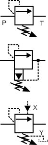
The top symbol indicates a simple, direct operated pressure relief valve. Note how the pilot pressure (shown by the dashed line) comes from the supply line, upstream of the valve. This indicates that as the pressure before the valve increases, it pushes the arrow against the spring and relieves the pressure in the direction of the arrow. The arrow is shown in it's deactivated position e.g. with the spring force higher than the pressure in the dotted pilot line.
The middle symbol indicates a pilot operated pressure relief valve. This valve operates in the same way as the top, direct operated valve except that it has at least two stages inside the valve, usually to allow larger flows. The pilot stage is shown by a black triangle. Note how the second dashed line shows how the drain, reference pressure is vented to the tank return line.
The lower symbol indicates a remote pilot operated valves. This valve will still open if the supply pressure increases, via the same dashed line, but will also open due to pressure applied on the remote line X. Note also how the drain line Y can be refereneced to a more stable drain line pressure.
Electrically operated pressure relief valve symbol
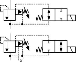
These symbols show similar valves to the ones above. Both still work as relief valves and will relieve the pressure when it gets too high but they also have an electrical load or unload facility. When the solenoid operated directional valve is closed (no flow path), the relief valve will operate as normal e.g. raising pressure. When the solenoid operated directional valve is open, connecting the relief valve pressure chamber to the tank line, this has the same effect as if the pilot relief valve was open, therefore the main stage opens and no pressure is raised. These valves are commonly used to load and unload pumps either for start-up or emergency stops etc.
The top symbol is normally open. The bottom symbol is normally closed and shows a two-stage pilot operation with an external Y drain. This is important for holding a constant or stable pressure because without it the balanced spring chamber pressure would be fed from the valve tank return line which could be subject to pressure peaks or oscillations.
Hydraulic pressure reducing valve symbol
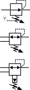
Pressure reducing valve symbols look very similar to those for pressure relief valves. This is because the valves work in similar ways except that the pressure sense line feeds from downstream of the reducing valve instead of upstream as in the relief valve. This means that the reducing valve controls the downstream pressure rather than the upstream pressure. As such the reducing valve cannot generate a downstream pressure that is not there but it can limit its value. Not how the arrow is shown in the middle positions indicating that it is normally open but closes the flow off when the pressure feed forces the arrow against the adjustable spring.
The top valve shows a direct operated valve with external Y drain line but only 2 ports.
The middle symbol has a third tank line port and arrowheads pointing in both directions. In this valve, if the pressure downstream rises above the reducing valve's setting then the valve will vent this pressure down the third line to provide a constant pressure in the sensed port.
The lower symbol shows a pilot operated version of the middle, direct operated valve.
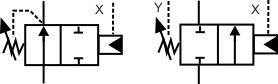
Hydraulic sequence valve symbols
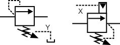
The symbol on the left shows a sequence valve with a manually adjustable set point and the one on the right has an externally controlled pilot switching pressure and internal drain.
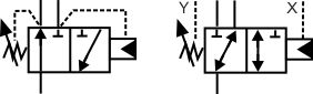
These symbols show 2-way sequence valves with an external pilot and internal drain on the left and external pilot and drain on the right.
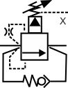
The third symbol image shows 3-way sequence valves with internal pilot and drain on the left and external pilot and drain on the right.
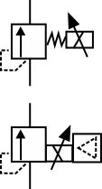
As symbols get more complicated engineers often recognise them by their functions. The left symbol shows a kick-down valve that would typically be used on a press to raise the pressure to a set point then unload the pressure until it resets.
The valve on the right would typically be used to hold the pressure on a clamp for example,e while the load pressure of a drill goes up and down.
Proportional pressure control valves
All pressure control valves operate in proportion to their pilot pressures, so the symbol does not include the extra lines around the box that designates the proportional version of a directional valve. The key difference in the symbol between the standard on/off electrical control and a proportional electrical control is the arrow through the solenoid and possibly the dotted triangle symbol to show internal electronics.
Proportional pressure reducing valves are very common on mobile control block as they are used to apply pressure on the ends of the spools that control the proportional directional valves.
What design type are these valves
 Are these poppet or spool style relief valves.