Symbols based on ISO 1219-1 and 2.
Only 4 simple components
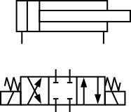
Hydraulic symbols provide a clear representation of the function of each hydraulic component. Laying each symbol out on the page in the same sequence the components are used in the circuit allows people to understand the complete function of the hydraulic equipment.
1. Poppet or check valves

Poppet, one-way, shuttle, or check valves are shown as a ball sitting on a seat. Pass flow through the seat and the valve opens. Pass flow from the ball side and the valve will close.
Poppet or check valves have a physical seat that the valve presses against. This positive connection may exhibit zero, or more likely a very small leakage across it.
In many cases, these are the cheapest and most simple valves but they also have the potential to be the largest, most complicated, expensive, and difficult to control.
2. Spools or pistons
Most hydraulic components are controlled when pressure is applied to one side of a piston or another. In the case of cylinders, the force generated by the piston will move and drive the load. In the case of a directional valve, the force is used to move a spool which opens different passageways to allow the fluid to flow along different pipelines.
Spool valves rely on tiny clearances to allow them to move freely. These spool clearances are small enough to hold the pressure but still large enough to allow a small amount of fluid to leak past. Cylinder pistons include seals which will exhibit much smaller leakages.
3. Orifice pressure drops
An orifice is just a small hole, either fixed or adjustable. With increasing flow across an orifice there will also an increasing pressure drop across it, this pressure is commonly used to open or close other spool valves or poppets. Alternately if a system has a specific set pressure then the orifice might be used to control the flow rate along its pipework.
Most holes are drilled have a definite length that will make them sensitive to fluid viscosity. Some holes have sharp edges making them insensitive to viscosity and shown by the sharp edges.
4. Spring forces
Springs are used to balance out the control pressure forces.
You can see springs used on one of the check valves and the ends of the spool valve.
Basic symbol shape meaning
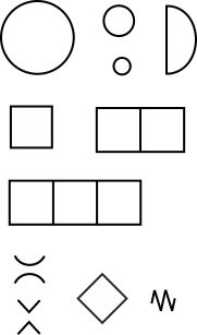
Circles and semi-circles represent rotary devices, either continuous, in one or both directions, or oscillating/reciprocal (semi-circle). The size represents the type of unit with a larger circle for a pump, the middle size a gauge, and the smallest size a roller.
Squares and rectangles form the basis of pressure and directional control valves. A single box for pressure control and multiple boxes for directional control.
Diamond shape boxes indicate a fluid conditioning device e.g. a filter or cooler etc.
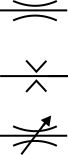
Flow control elements are shown by back to back semi-circles (viscosity dependent) and arrowhead Vs (viscosity independent).
The saw tooth symbol represents a spring.
Combine symbols to make valves
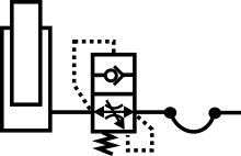
Connect the symbols with lines that represent passageways and we have a larger valve.  Can you describe the functions this valve has and how it will perform. This may be a complicated and unusual valve but if you look at each component separately you can soon work out its function.
Combine symbols to make circuits
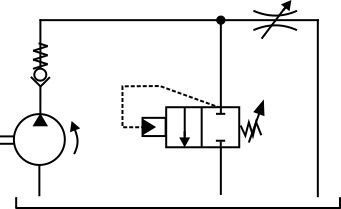
Connect the symbols with lines that represent the pipework and we have a circuit. We've added a pump to provide the flow but can you describe how the circuit will perform.