Learn about the different hydraulic components.
Self-study lesson plans and training record download page.
Power is transmitted through the hydraulic fluid
Hydraulic fluid is assumed to be incompressible. Apply a force at one point in a hydraulic circuit and the same force can be used in any other part of the circuit.
Inefficiencies in hydraulic power transmissions tend to be slightly higher than for mechanical or electrical drives but hydraulic systems have a far higher power density and flexibility. That makes hydraulics the only options for many applications such as mobile excavators where high power is required to move equipment in lots of directions but with minimum size and weight.
Pumps supply hydraulic fluid
Hydraulic pumps attached to engines or electric motors provide the fluid flow.
They don't create the pressure as this results from the system loads or control valves.
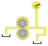
Fixed displacement pumps provide flow directly proportional to the speed they are rotating.
Gear, vane and piston pumps can be fixed displacement.
The gear pump shown will rotate forcing fluid along the pipe. The gauge measures the hydraulic pressure in the line created by the resistance against that flow.
Variable displacement pumps provide flow relative to their speed but also have controls to reduce the flow when it's not required.
Actuators drive the loads
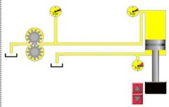
Hydraulic cylinders or motors convert the hydraulic energy to a mechanical movement to drive the loads.
The flow provided by a pump will enter either the bore or rod side of the cylinder to make it move down or up. Notice how only raising the cylinder requires work. Lowering would still need to hold the load up. When designing a hydraulic circuit it's vital to fully understand the load in order to control it safely.
In a perfect world, our cylinder would give as much work out as the pump puts in. However, all hydraulic systems exhibit some losses through either leakage or heat and much of our design effort is focused on reducing these. Even in the simple circuit shown we will have small volumetric flow and mechanical efficiency losses in the pump and frictional losses in the pipes and cylinder seals.
Valves control the fluid direction

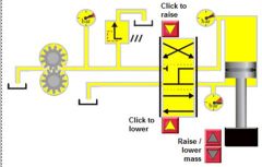
To control the actuator movement direction we will need a hydraulic control valve. In this example, we have a 4 way 3 position directional valve, this means it has four ports and can be switched into 3 different positions. In the middle position shown the valve is closed so no flow can get through the valve. Note how the A and B lines are both connect to tank so there is nothing holding the cylinder up and would fall.
The upper and lower valve positions would connect either the cylinder bore or annulus lines to the pump supply allowing the cylinder to be pushed up or down
Pressure relief valves provide safety protection
Finally, as I'm sure you noticed, the above circuit would be highly dangerous. With a fixed displacement pump and nowhere for the fluid to go the system would soon fail in a very dangerous manner. To ensure safe operation we must put a pressure relief valve before the control valve. This will release the flow when it gets to the level set on the pressure relief valve.
Again this is not a good design as too much energy would be wasted while the valve is closed and the pump is sitting on full pressure and full flow.