Self-study lesson plans and training record download page.
Caveats and Qualifications
Always apply common sense and ask lots of questions.
Every industry, application and situation is different so no amount of experience or training will cover every possible situation. The information provided in this training module is designed to cover the basic principles and how to apply them. It is by no means an exhaustive list and will not be relevant to all applications, or be a replacement for common sense.
Design Features that Effect Maintainability
The hydraulic equipment design will play a major part in how it is maintained. There are also significant differences in what each piece of equipment is required to achieve. For example, a simple lorry lift may only work for a total of 250hrs throughout its life, requiring little maintenance and get changed for a straight replacement unit if it ever breaks down. A power unit in a steel mill, on the other hand, must work reliably for 10,000 hrs and high downtime costs will mean that regular maintenance is always cheaper than waiting for it to break down.
Contamination Control
Understanding the equipment's environment and duty are key to specifying the features required for it to achieve the necessary service life. With 90% of failures resulting from contamination in the hydraulic circuit, it should be obvious that making sure as little dirt as possible gets into the system and ensuring as much as possible is filtered out, are key maintenance rolls. This means that monitoring the fluid cleanliness is always the number one priority.
a) Establish the manufacturer's maximum ISO cleanliness level requirements for the components used.
b) Check the filter rating and fluid flow is sufficient to achieve the required cleanliness in the installed environment. You may need the filter manufacturer's advice or trials with an inline contamination meter to fully understand the nature of the contamination movement throughout your system.
C) Keep a record of the equipment operating history noting any measurements, conditions, failures, and filter changes etc.
The best way to monitor the fluid condition is by using a modern inline test meter. If the results are high then you can complete a material analysis on the deposits to identify which components are starting to fail or where else the dirt may be coming from.
Hydraulic Reservoir Facilities
Reservoir design is a key area where additional maintenance facilities can be included or left out.
The size of the reservoir relative to the pump flow rate and the shape of the baffles and bottom of the reservoir will also affect how the contamination settles out as well as how stable and even the fluid temperature will remain.
New fluid should never be simply poured into the reservoir and its good practice NOT to have any access point where people can do this. Instead, the fluid must be pumped into the reservoir via a filter then flushed within or throughout the system until it's is clean. New fluid is not clean.
A useful feature could be anti-syphon facilities and isolators to prevent the reservoir draining when components are removed. Engineers will need to be aware of the installed height of all components and may need to break the seals of a fitting on top of the reservoir, to prevent the fluid syphoning out.
The reservoir should be an integral part of the fluid conditioning system, provided it is sized and used correctly. Its functions include temperature control, contamination control, air bubble settling and a stable pressure signal reference level.
Air or Water in the Fluid
Check for the appearance of air bubbles or moisture in the fluid, both of which can cause a milky appearance, although you may require a clear return line hose to see this. Air is removed when the fluid is allowed to settle and water can be evaporated out by heating, but both will damage the components. Cavitation noises in the pump or valves may indicate their presence but it's important to find and eliminate their source.
Air bubbles can be caused by a leaking suction line or poor tank return line conditions where high fluid flow causes turbulence in the reservoir which is then drawn back into the pump.
Water in the oil may be caused by a crack in a water cooler or more commonly by condensation collecting on the roof of the reservoir after being drawn in through the air breather.
Hydraulic Filters Maintenance Facilities
Regularly monitor the filter clogging indicators to check their condition, particularly at cold start as the thicker fluid may be an early warning for when things are changing. Designers will never know everything about a system before it's built; the actual filter effectiveness will depend on duty and changing environmental conditions throughout the year so plan your filter changes based on what happens due to your unique operating conditions; don't just leave it until the manufacturers recommended change period has ended.
Consider using electrical indicators which will automatically identify all high-pressure drop situations.
Changing filter elements can often be difficult due to limited access when removing the long filter bowls and elements. Ideally, you will be able to remove the filter and its bowl to allow the container to be cleaned while the element is replaced, however, if access is difficult, there are now other top entry systems available that may make the process easier.
Fluid quality and working life
Overheating fluid or applying too high a pressure difference and therefore creating a high shearing effect on the fluid, will degrade its properties and shorten its life. Take good care of your fluid if you want to look after your components.
If the fluid is damaged then it should be replaced but if fluid conditions are good then keeping the existing clean fluid may be preferable to changing it with new, but less clean fluid.
Electric Motors Design Maintenance Considerations
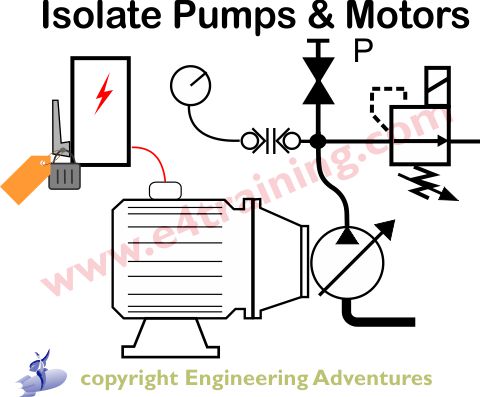
As the primary power source, it is vital that the supply to the electric motor is always turned off, locked in the isolated condition and "tagged out" with a sign to say the system is being worked on.
Always initially kick the motor over for a very short period of time to check the direction of rotation is correct, whenever the supply has been newly connected. Running a hydraulic pump in the wrong direction for even a short period of time can cause terminal damage.
DC motors present considerably more challenges to designers than AC motors and therefore the risk of in-service failures is far higher. DC motors come in a range of duty ratings and if conditions or usage falls outside of their design limits then their operating speeds can vary. When pump speeds vary there is an increased chance that the systems will perform outside of their expected limits or the life of the pump may be significantly reduced.
Hydraulic Pumps Maintenance Considerations
Ensure good suction conditions; ideally a positive pressure head. Suction heads can be adversely affected by the reservoir fluid levels, suction pipe restrictions, dirty suction filters, leaks in suction pipework, high air breather pressure drops or higher than normal dynamic flow rate changes. Low fluid temperature, particularly at start-up, is another potential risk point.
Consider the pump type being used. Piston and vane pumps require perfectly clean fluid but will not generate extra dirt if they are not damaged. Gear pumps may continue to operate in dirtier fluid but will always generate some dirt themselves, making the overall system much less reliable and reducing pump and component lives.
Gear pumps should never be taken above their factory design and test pressure or they re-cut themselves in, which can then generate and send excessive contamination into the circuit.
The case drain line in some pumps and motors provides a great way to check the condition of each component. Increases in flow or temperature may be the first clear signs of more serious concerns within the pump.
Maintaining a consistent and low case pressure is vitally important to the health of a pump or motor. Generally, flow rates are low and fairly constant, however, most pump controllers exhaust the control flows into the case and some to these can be surprisingly high. It's often worth checking the case drain performance under all working conditions to make sure the return pipework is sufficiently sized.
Hydraulic Actuators Maintenance Considerations
Before any maintenance work is started, all actuator loads must be supported or locked in place so that they cannot move. If the load is allowed to move one cylinder then this can create pressure and flow inside the system which may move another actuator when people are working.
Hydraulic actuators, particularly cylinders are generally one of the main entry points of contamination into the system. Contact of the cylinder rods with the air will draw in contaminants past the seal. Try to keep the cylinder rods in as clean an environment as possible and store the cylinders in a retracted position when they are not being used to avoid additional contaminants settling and corroding the exposed rods. Rotary motor seals are less likely to draw in contaminants than axial seals but can still be a source of dirt ingress.
Side loads on cylinders will cause additional rubbing of the cylinder wear rings and seal which in turn may cause additional contaminant to be generated. Keep the cylinder clevis balls lubricated and make sure actuator side loads are kept to a minimum.
Be very careful not to trap pressure inside cylinders by isolating them during downtime or maintenance. Small temperature changes can cause significant internal pressure variations which frequently lead to distorted and inefficient or inoperative cylinders.
Cylinder seals and wear rings are generally the first part of a cylinder to fail and while changing them is not easy. It can be very cost effective compared to a full cylinder replacement.
There are a wide range of cylinder styles available ranging from welded bodies to more robust Mil specification. The selection should have been made to ensure that the required life is met for the minimum cost, however, if the duty or environment are more severe then higher specification cylinders may be required.
Directional Control Valve Maintenance Considerations
Directional control valves rely on spring forces to return their spools to the standby condition. With higher levels of contaminated fluid, there will always be an increased possibility of the spools sticking and the system exhibiting either intermittent or incorrect operation. Other factors that affect this tendency for the spools to stick are the level of vibration and the amount of time that the spool sees a high-pressure drop across it.
On mobile equipment, such as tractors, there will always be a high level of vibration so engineers can get away with running more contaminated fluid before the valves start to stick. In smooth, industrial environments the fluid needs to be very clean as there is no constant shaking to release the spools.
If spools see a high-pressure drop across their lands for a long period of time there will be significant levels of leakage that will draw in extra contaminants to block the valve. This will lead to much lower reliability than a system with a high-pressure drop across a spool for only a short period of time.
The above factors mean that maintenance engineers must understand their own unique machines to evaluate which parts are likely to fail first and how they could improve the situation.
Spool valves can last for over 30 years if the fluid is kept clean although life is generally quoted as 1 million cycles due to solenoid life and seals etc. Dynamic seals, as used to reduce leakage on some pilot lines, for example, are one component that will wear and will need to be replaced at or before the million cycle mark.
Proportional and Servo Valve Maintenance Considerations
Proportional and servo valves contain very accurately machined control lands that generally have higher pressure drop and therefore wearing forces, across them. This valves will need to be replaced more regularly, probably based on how accurately they need to control.
Flapper style or high-performance servo valves will also need to be serviced more regularly but this can only be done by an appropriate agent. Servo valves require special testing and setup equipment and procedures that are generally only available through the original manufacturer or specialist agents.
Pressure Control Valve Maintenance Considerations
Often, safety relief valves never operate because they are only required when other valves fail, which they seldom do. They are also very difficult to check or test because they may only function at pressures above the other control valves or pump rating. There is no easy solution to this. In the past, it was common to remove relief valves every year to re-check their pressure setting but modern thinking is that this just risks adding additional contaminants and increasing the risk of failure. I situation needs to be considered carefully but it may be possible to increase the system pressure via other components or lower its pressure and then reset it based on the pressure increase per fraction of turn.
No modern relief valve poppet should ever be tapped with a hammer to reseat it. This is an out of date practice from when valves were not as well made and circuits were much less clean.
If pressure control valves start to oscillate badly then make sure the circuit is bleed of air and check the system natural frequencies (hit load with a "hammer" and measure the pressure ripple). If all else fails then ask the supplier if they have a more stable version.
Be aware that adjustments to pressure control valves in one point of the circuit can and affect the flows and pressure in another part of the circuit. All system pressures may need to be rechecked once adjustments have been completed.
Accumulators Maintenance Considerations
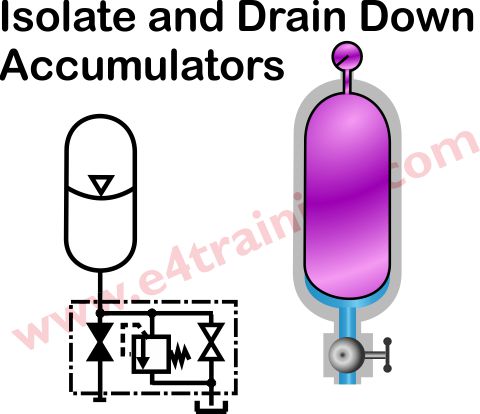
Supply accumulators must always be fitted with an appropriate safety block and this must be used to isolate and drain down safely before any work on the system begins. Accumulators are devices that store energy and therefore pose a particular safety hazard. Accumulator safety blocks require sealed, certified relief valves which must not be reset or adjusted.
Bladder accumulators should be fitted vertically as bladder life is reduced when they are on their side. The nitrogen precharge pressure should always be checked under the similar ambient conditions as temperature does affect the pressure. Accumulators' will require occasional re-charging using the appropriate recharge valve kit. Always follow the manufacturer's specified procedure if you need to change the bladder, e.g. if regular recharges are needed or the performance changes.
Hydraulic hoses Maintenance Considerations
Hose life depends on the environment and duty. The recommended replacement may be as low as every 3 years with a probable maximum of 7 years. The potential injury risks from a hose failure generally make replacement a sensible economic decision.
There are a number of actions that can be taken to ensure you achieve the best possible hose life. The correct hose assembly procedure must always be adhered to and enclosing the hose in a sheath will also help protect it from the environment. Make sure the hose does not rub against other objects and if it cannot be properly guarded then consider tethering the ends if it is mounted in a location where failure could result in injury.
General System Maintenance Facility Considerations
There a many features or facilities that can be included within a hydraulic system to aid maintenance and reliability. These include:
Doubling up on components to allow switching between each one during maintenance or breakdown.
Adding extra isolators to make flushing or maintenance easier. Never put isolators to return lines as someone will always leave them closed. In fact, extra isolators will probably increase risks rather than reduce them. Hydraulics in inherently safe because the pressure generally vents away when the supply is turned off. Adding isolators can trap the pressure inside the pipes and brings the risk of high pressure coming from temperature changes. The safest approach is always to switch off and isolate the supply then fully vent the system before starting any maintenance.