Understand the scientific laws that make fluid power work and some basic pressure formula.
Self-study lesson plans and training record download page.
Pascal's law or Pascal's principle
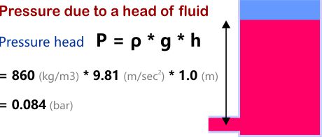
Pascal's law states that a change in pressure at any point in an enclosed fluid at rest is transmitted undiminished to all points in the fluid.
In mathematical terms, this is defined as Pressure = Density x gravity x fluid height
In practice most hydraulic fluid is not at rest and the head height changes are only significant when considering pump suction pressure in the reservoir.
Equal pressure at all points
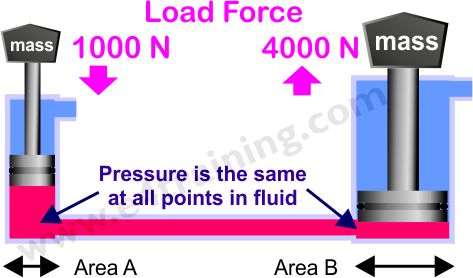
Working pressure is transmitted by the fluid to every other part of the system. This is the fundamental principle that enables fluid power to work.
If a small cylinder with a small load creates the same pressure as a big cylinder with a big load, then the loads will be balanced. However, if one cylinder creates a higher pressure, this cylinder will lower and push the other side up.
Hydraulic jack calculations
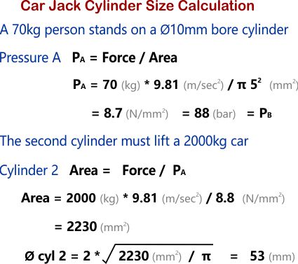
Let us consider how a small person can lift a heavy car, armed only with a hydraulic jack.
Calculate the size of the second cylinder that is required to give the appropriate mechanical advantage for a 70kg person to lift a 2000kg car with a 10mm diameter hydraulic cylinder.
The load sets the system pressure
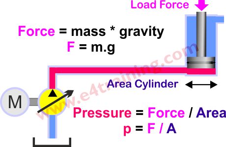
The FORCE provided by an actuator is equal to the PRESSURE applied to the actuator multiplied by its effective AREA (F=p*A). This means that the more pressure or the larger an actuator, the more force you have. However, normally in practice the load applied onto the system sets the pressure so is our starting point for the calculation, therefore we should probably say the pressure p=F/A.
The major benefit of hydraulic, fluid power systems over other drive systems are their very high power density capabilities. A small pump, motor or actuator can transmit much greater power for its physical size than the equivalent sized electric motor.
Pressure losses in control valves
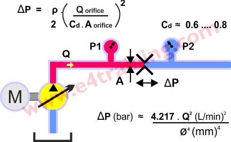
The force generated by the actuator will always be lower than that available from the supply pressure; there will be a number of pressure losses from within the system itself. The largest of these is likely to be the flow control valve pressure drop. In order to control the actuator speed, we normally add a small orifice to limit the supply and/or return flow. This orifice will generate a higher pressure drop across it the greater the flow becomes, until finally the supply pressure, orifice pressure drop and load pressure become fully balanced.
The energy loss caused by the orifice restriction will be converted into heat within the fluid. While these losses are not ideal you will typically need a higher pressure drop to give better actuator control.
Elastomer seal friction pressure losses
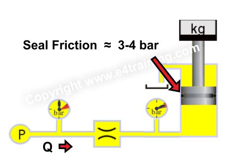
Nearly all actuators and many valve spools contain elastomer or similar material seals to reduce leakage. However, because seals have face to face contact they will also cause a small pressure loss due to friction. Cylinder seals, for example, will typically generate a 3-4 bar pressure loss e.g. you will need to add 4 bar to the cylinder load pressure before it will start moving.
Pipeline pressure losses
Most hydraulic systems are designed with the pipework sized to give standard fluid velocity values. For this reason, we don't normally need to worry about pipeline pressure losses. However, it can be important to know what your line losses are, particularly if you have long pipe lengths or low-pressure pilot or return lines where small losses are still high compared to the actual working pressures.
Fluid flow in pipework should be laminar (Reynolds number below 2000) although may exceed this for short lengths inside manifolds etc.
Summation of pressure
Total losses in single pipework are added together in the same way as series resistance in electrical systems. Parallel restrictors would are added as parallel electrical resistors.
Supply Pressure = Load Pressure + Valve Pressure Drop + Seal friction losses + Pipeline Losses.
Of course, the above equation assumes there is no significant tank return line pressure. If the cylinder has meter out control or the exhaust line pressure is above atmospheric pressure, then you must add this to the equation, times piston area ratio.
Measurement and instrumentation errors
Always keep your in sensors in calibration date.
Always pay attention to their minimum resolution, offset or sensitivity. A 600bar transducer s likely to have a 6 bar minimum resolution, which may be fine when measuring 315 bar, but could read 12 bar instead of 18 bar at low pressures. A 25 bar transducer would read the correct 18bar.