Self-study lesson plans and training record download page.
Overpressure protection
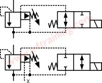
It is vital that every circuit includes some form of overpressure protection, as well as the pump's pressure compensator.
In many situations, the system will also include an electrical unload system whereby the pump cannot raise pressure unless the electrically operated relief valve is activated. The image shows both a normally unloaded and normally loaded relief valve because in some situations it may be considered more dangerous for the circuit to switch to a failsafe condition with no pressure than one with pressure.
Guard interlocks
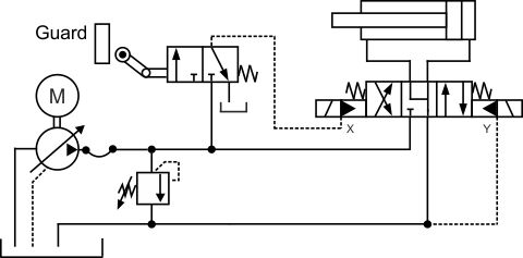
Many modern hydraulic systems include electrical limit switches to prevent the hydraulic system operating while the safety interlocks are not in place. However, although electrical switches are generally cheaper to use than hydraulic interlocks, there are situations, such as hazardous environment or highly critical applications, where 100% hydraulic safety interlocks are required.
This circuit shows how a hydraulic roller interlock switch might be used to only allow pressure to the directional valve pilot system when the guard is in place. This means the cylinder cannot be operated unless the guard is secured.
Two hand operation
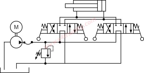
Sometimes the operator is required to use both hands to start the machine operation. This may be to ensure that the operator cannot hold a piece of metal in his hands as a press comes down, for example. The open-centre valve circuit shown would only operate when both valves are manually switched. Until that point, the pump flow will always pass directly back to the reservoir and not generate any pressure.
Supporting the load safely
All loads that are supported against gravity will need some type of load-holding or hose burst valve. These will support the load when it is not being driven up or down, allow it to be driven up and don smoothly or protect the load from falling if the hose breaks. If the equipment is used to lift things near people then it will probably require some form of legal compliance such as LOLER in the EU. Hydraulic load holding is a complicated subject and we have a separate section to cover this here
Accumulator safety valves
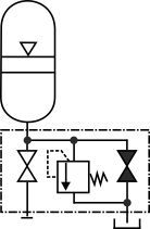
Accumulators store energy and are therefore potentially one of the most dangerous components in any hydraulic system. It is a legal requirement in Europe and the US that supply accumulators are fitted with a certified safety block to allow them to be drained down safely when the system is turned off.
Standby creep
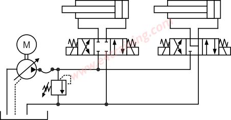
I can be dangerous if the cylinder gradually moves or creep while the hydraulic system is in standby mode. In this circuit, we see that the centre layout for each directional valve is different. On the right-hand valve, both of the cylinder lines will be at the tank return pressure so the cylinder seal friction should be higher than the forces being generated.
In the left-hand cylinder lines, the pressure can be half of the supply pressure, therefore, creating much higher forces than the seal friction. Because the bore area is higher than the annulus area the cylinder will try to gradually extend, even when the directional valve is in the centre position.
This can also happen behind check valves if one leaks more than the other.
Pressure intensification
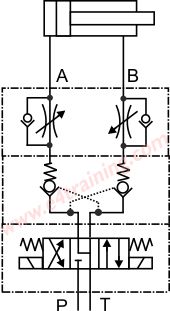
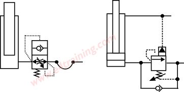
With meter-out flow control, as shown in this image, when the cylinder is driven out against the flow control valve, the bore pressure will the same as the pump pressure and the annulus pressure could be twice the bore pressure when using a 2:1 area cylinder. This can be very dangerous if the cylinder and components are not rated to the higher, intensified pressure.
Thermal pressure expansion
A 15 degree C (27F) change in temperature can cause a 1% expansion of a typical hydraulic fluid. If the fluid is held within a trapped volume, such as between the check valves shown in the above image, then the pressure may increase by 150 bar. This means that the simply by leaving your hydraulic system out in the sun for 24 hours may be enough to over-pressurise the components and damage the cylinder or create a failure safety risk.
This type of failure does happen and many applications include thermal relief valves to prevent it. However, there are many applications, including lots of OEM mobile machines, that don't include any protection but still don't appear to suffer from failures. It's likely this is because on a system with a hydraulic hose or long lengths of relatively thin-walled pipework, this expands to relieve the pressure plus lower cost check valves tend to leak with a few drops of fluid, which is enough to prevent excessive pressures. On higher performance systems the pipework may be shorter and more solid plus the better quality check valves less likely to leak. In these situations a thermal relief will be required and a cost-effective way of preventing the risk. Certainly, if you have a cylinder full of fluid that is sealed with plugs in its ports, then it will over-pressurise and deform very quickly.
Shock loading
Anything that can lead to a failure is a safety risk. Shock loadings on hydraulic systems create high internal pressures peaks that can eventually lead to catastrophic failure of components. These load conditions may not always have been apparent to the equipment designers so they may not have taken sufficient precautions at the design stage.