Self-study lesson plans and training record download page.
Keep it simple
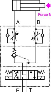
Always try to keep the circuit design as simple as possible. In this circuit, we don't need any pressure control because the cylinder has been specified to work safely within the supply pressure. The load is only in one direction so we just need one PO check valve. This reduces the risk of trapped in pressure and by using the A and B to T spool we also reduce the risk of cylinder creep. We have meter-out flow control to regulate the cylinder speed in both directions.
Unfortunately, we cannot use this layout in every application. The following paragraphs will look at other options and discuss some of the reasons why certain circuits will have been designed differently. Make sure you are familiar with our 'understanding loads' section before reading about circuit design because many of the changes will be as a direct result of the loads that are acting on the system.
Directional control valve options
Many of the key directional valve features will probably be based on maintaining commonality with other valves in the factory to reduce the spares requirement and reduce maintenance issues.
Sizing is a simple flow rate matching issue but duty and life cycle can be far more complicated to predict. Experience of different valve types in the environment is key here.
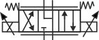
Valve centre condition will be based on the pump supply type and what cylinder loads are present during standby. It is better to completely vent the A and B lines rather having them closed when you can never be sure exactly what pressures will be seen there. Venting also prevents thermal pressure increases because the natural leakage will always relieve this. Often there are general operating procedures that should make sure the cylinder is always returned to a safe condition when not in use, however, these can be ignored and are often not possible during maintenance or commissioning, etc. For example, the simple circuit shown could be held with the cylinder at maximum extension and locked in place with the check valve. This situation would have no facility to relieve the excess pressure if the trapped in fluid was subject to a daytime temperature increase. A similar situation could occur if the cylinder lines were blanked while maintenance was taking place. It is often failures due to these unusual or extreme conditions that lead to circuit modifications being made and then forming the standard designs for the future.
Switching speeds may need to be controlled to reduce noise. Many small, direct-acting valve circuits don't need to be damped as the shock loading does not cause any major noise or reliability issues. However, as flows and masses get larger, and two-stage, pilot-operated valves are used, then noises and shock loads are likely to be higher. Fortunately, the pilot systems in these larger valves are easier to regulate with different control pressures, spool damping or supply notches.
Flow control valve options
The biggest concern when trying to control the movement of a hydraulic cylinder is avoiding negative load pressures. We always prefer to brake the load than restrict the flow that supplies it. If we don't always make sure that the load restricted from moving by an orifice on the contracting side then we risk seeing negative pressures on the expanding side. This is the reason we always say 'if in doubt, meter-out'. Of course, there can be situations where perhaps there is no risk of negative pressures and intensification is more of a risk, in which case meter-in flow control could be a more appropriate solution.
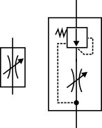
An orifice is used to control the flow rate and cylinder speed. The flow is directly proportional to the square root of the pressure drop across the orifice, therefore, when the load pressure or supply pressure change, the flow rate will also change.
If a more consistent flow rate and cylinder speed are required then a pressure compensated flow control valves (shown on the right) can be used. These valves maintain a consistent pressure drop across the orifice and therefore a much more consistent flow rate. The potential drawback from using this type of pressure compensated valve in some systems is that by restricting the flow rate to a maximum level the valve entry can induce the maximum supply pressure when only a small load pressure is required. There will also always be a fixed pressure drop of around 15-20 bar across the valve which again may adversely affect system operating efficiencies.
Proportional control valves
If more flexible, electrical flow control is required then it's likely the use of a proportional flow control valve, instead of the directional valve, would be most appropriate. The entry and exit orifice sizes are controlled with a single valve so we still maintain good braking control of the load. In fact, the spool lands can be biased to provide more restriction on one side than the other and therefore compensate for the lower annulus flow than bore flow. A basic proportional valve will still be sensitive to load pressure changes in the same way an orifice is. However, proportional valves are commonly used with an integrated pressure compensator to provide the constant pressure drop across them and therefore consistent flow rate through them.
Pressure relief options
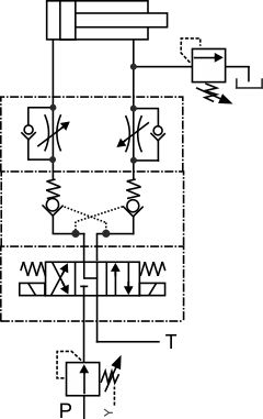
If the cylinder is held in position by two check valves it is prudent to add a thermal relief valve to protect against pressure increases due to temperature increases. One valve will relieve both sides of the cylinder.
If the cylinder might suffer from shock load impacts then a relief valve should also be added in the location shown, although dependent on which direction the load might act. It's likely a direct operated valve will be used in each case as these tend to exhibit very low or zero leakage, therefore reducing the likelihood of cylinder creep.
Pressure reducing valve options
In most applications, the cylinders are sized to give the correct force at the maximum supply pressure. Engineers can't add pressure relief valves at the cylinder to limit the pressure if the setting needs to be below the supply pressure, or the fluid would simply leak out.
If a lower supply pressure is required then a pressure reducing valve can be added into the supply line of the directional valve. This can be a simple solution to overcome the risk of intensification and should ensure that the cylinder never exceeds its design limit. Unless the reducing valve fails; which is always a risk it's better not to take.
Load holding options
Load holding is a complex and varied subject that we have covered in a separate section here