Read in conjunction with simulation experiments.
Self-study lesson plans and training record download page.
Hydraulic check valve operation
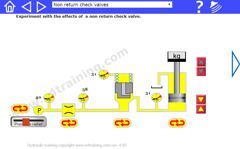
Hydraulic check valves only allow flow in one direction. Select the 'Non return check valves' simulation from the top drop down menu.
They operate because when pressure is applied to one side of the valve it opens and when pressure is applied to the other side of the valve it closes.
In our example, we show a poppet sitting against a seat although it may be a spool opening and closing a port or a simple ball against a hole. Most check valves have a spring to regulate the pressure at which they open although others have no spring and just rely on gravity or flow to close them.
Key performance factors
The pressure acts on the seat area to either lift or shut the valve. The spring provides a minimum opening force. The flow path through the valve is the restriction that limits the maximum flow or creates a pressure drop that is no longer available to drive the load.
The operation can change due to flattening of the sharp-edged orifice. This changes the area that the pressure operates against and may result in flow forces across this flattened area trying to close the valve. Simple designs are also likely to have more flow forces acting on them although their function is generally so simple that it should not make any difference.
Pilot operated relief valve operation
If a check valve was used to spill fluid into a third, drain line then it will become a simple relief valve. They operate in the same way. However, as a relief valve the check valve opening pressures would only be low and its operating characteristics poor.
Direct-operated relief valves have smaller seat areas and larger springs to achieve the pressure levels required. However, the small holes mean that they cannot pass high flows and the flows they do pass are likely to see poor flow characteristics.
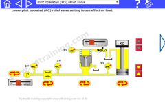
In our example, we show a pilot-operated relief valve. In this valve, we have a small direct-operated relief valve that sits on top of the main stage. Now the small relief valve need only pass a small flow to open the main stage so it will have a more stable, flat characteristic. The main stage of the relief valve is also a larger diameter so will pass more flow without suffering from flow losses and higher valve pressure drop. Also, the control springs for the smaller pilot relief valve can be much smaller and the larger, main spool valve spring much lighter, both of which improve reliability.
Key performance factors.
The pilot valve operates with the same parameters as our check valve. The detail in its design will have the same effect on its operating characteristics.
The main stage has three pressure areas that affect its performance. The nose area, the larger, full diameter area at the back of the spool and a third area that is the difference between the nose and spool outside diameter. There is also an orifice between the pilot relief and pressure sensed line.
When shut, the supply pressure is seen on the back and nose areas. The outer nose area is low so there is more force keeping the main spool shut. The spring only assists keeping the valve shut. When the pressure reaches the setting of the pilot spring, the pilot valve opens. This unloads the pressure behind the main stage spool, which lifts the valve and allows flow to relieve into the drain line. The orifice creates a pressure difference across the spool element, this helps to keep the main stage open and achieve a superior 'pressure vs flow' characteristic.
A key issue with pilot-operated relief valves is that because the spool element with a small clearance, it will always allow some leakage from the main pressure line to the tank port. Although this may be small it does mean that fluid will leak away from the loaded side of a cylinder and therefore the cylinder will creep. By contrast a direct-operated relief valve usually has a positive poppet seat which should not leak, or certainly not as much.
Pressure reducing valve operation
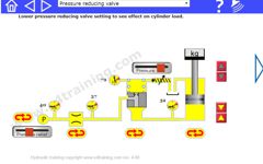
Reducing valves keep the downstream pressure, after the valve, constant by shutting the supply flow from the valve when the downstream path becomes blocked.
They work because the downstream pressure acts against the spool element to shut off the supply flow.
In our example, we see a pilot operated reducing valve. The pilot is the same relief that we saw in our pilot-operated relief valve and it still acts on the back of the spool element. But now the flow is supplied through a port in the side of the spool and the pilot pressure is sensed from the outlet port, downstream of the valve. Now we have an orifice between the valve outlet and pilot valve to ensure that pilot flows are only small. Pilot flows are a loss or inefficiency in comparison to the overall operating system.
Key performance factors
Direct-operated reducing valves are available and while they have less leakage, they can be less stable and only available for lower flows. Spool elements mean that reducing valves are not generally leak-free.
Reducing valves utilise proportional spools to control the flow rather than poppets to simply open at a set point, preferably independent of flow. The pressure areas act on the full areas of both sides of the spool.
Pilot to open logic valve operation
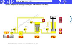
Pilot to open logic valves Open the flow path when they have pilot pressure and shut the flow path when they don't have pilot pressure.
They operate because a pilot pressure, equivalent to the highest supply pressure, is applied to the largest spool area and is therefore dominant in controlling how the spool is moved. In the case of a pilot to open logic, the pilot pressure forces the logic valve to open.
In our example, we show the logic valve poppet acts like a reversed direction check valve and stops the flow from moving forwards through the circuit. Applying a pressure from the pilot supply to the main spool area will open the seat and allow flow to pass, whatever the line pressures are.
Key performance factors
The highest pressure always applies to the largest area so will always dominate. The valve will backflow if no pilot pressure is applied.
Logic valves may have sealed spool elements to minimise leakage or they may have normal spool clearances. If seals are used then there will be more hysteresis and reduced life cycles.
Pilot to close logic valve operation with unbalanced and balanced spools
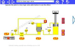
Pilot to close logic valves shuts the flow path when pilot pressure is applied and open the flow path when pilot pressure is removed.
They operate because a pilot pressure, equivalent to the highest supply pressure, is applied to the largest spool area and is therefore dominant in controlling how the spool is moved. In the case of a pilot to shut logic, the pilot pressure forces the logic valve to close.
In our example, we see that the logic valve poppet acts like a normal check valve that allows flow to move forwards through the circuit. Applying a pressure from the pilot supply to the main spool area will shut the logic valve seat and stop flow in the line.
Key performance factors
The highest pressure always applies to the largest area so will always dominate. The valve will not allow forward or backward flow when the pilot is applied.
With the unbalanced design, it is possible that the load pressure increases above the supply pressure. Because the load pressure is applied to the area between the nose seat and spool OD, this can add to the nose pressure and open the valve.
With the balanced design, load pressure does not apply to any area so the valve will operate independently of load pressure.
Logic valves may have sealed spool elements to minimise leakage or they may have normal spool clearances. If seals are used then there will be more hysteresis and reduced life cycles.