Typical Problems and Potential Solutions
The most common problem experienced with counterbalance valves is instability.
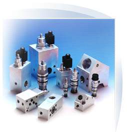
Sun offer a large range of different types of counterbalance valves to try and satisfy the wide range of application problems.
Techniques for overcoming instability
Most applications will work with the standard 3 port counterbalance valves but it is useful to have other cartridges to try which will fit into the same cavities when problems do arise.
Simply trying different types of cartridges does not appear to be a very scientific method of finding a solution but often is the quickest. The problem particularly with many mobile applications is that there are so many changing parameters such as variable speeds, loads and geometry that it would be virtually impossible to find solutions with either calculation or some form of computer simulation.
The problems appear generally in two main forms, instability and/ or noise. Often however the problems only occur intermittently and under certain operating conditions. It is important to obtain as much detailed information about the conditions when problems occur to enable a satisfactory solution to be found. Sometimes compromises may need to be made as the solution to the problem may affect the efficiency of the machine in other operating conditions.
It is important to mention at this stage that it is wrong to assume that problems of instability are always due to the load control valve. The two most common alternative causes of instability are trapped air and cylinder seal stick- slip.
Instability At Low Flows
On a number of mobile applications it is required to operate actuators over a wide range of speeds and down to very low speeds requiring very low flows.
The problem this creates is that the opening on the counterbalance valve is so small that it is very difficult for it to modulate and will have a tendency to open and close at a high frequency causing unstable movement of the actuator.
To help overcome this problem Sun has developed Restrictive and Semi-restrictive cartridges that fit into the standard series cavities but have reduced area flow paths on the nose end of the cartridge. This means that at lower flows there is a greater opening of the cartridge and therefore the valve modulates better and is less likely to be unstable. The reduced area does mean an increase in pressure drop with flow and therefore this may cause a problem at higher flows. As an approximation the pressure drop with the semi-restrictive cartridges is the same at half the rated flow compared to the standard cartridge, while the pressure drop with the restrictive cartridge is the same at a quarter of the rated flow compared to the standard cartridge.
These cartridges are available on series 1,2 and 3 but are most commonly used on series 1. The semi-restrictive cartridges can also help on general unstable operation because the additional pressure drop creates greater stiffness in the circuit.
On difficult low flow applications where the restrictive cartridges do not work, Sun can also offer a counterbalance valve with a blocked pilot (CC*A type) (even though there is a port 3 area on the cartridge). This now becomes a load control valve without a pilot, creating a continuous back pressure so it is less efficient but unlikely to be unstable. This valve can also be used effectively on applications where the load is constant so that there is no real advantage having an external pilot.
Other possible solutions
If none of the above alternative solutions solve the general instability, there are modifications to the circuit which may help.
1. Adding a very small accumulator into the pilot line of the counterbalance valve helps to dampen changes in the pilot signal.
2. Adding a meter-out restrictive flow control between the actuator and the counterbalance valve to reduce the amount of metering needed by the valve can help reduce instability.
3. Adding a small direct operated relief valve to the pilot line to limit the maximum pilot pressure to help to prevent over opening with high inertia loads. It would also require a small restrictor in the line to limit the flow to the relief valve.
Instability Due To Changing Backpressure
The most common applications where this problem occurs are when counterbalance valves are used with pressure compensated proportional valves and in regenerative circuits.
1. Most applications where pressure compensated proportional valves are used involve metering out of the actuator down stream of the counterbalance valve. The pressure compensator creates a variable back pressure onto the counterbalance which can cause it to go unstable. It is basically the counterbalance valve and the compensator interacting with each other. This problem can normally be overcome by using a vented counterbalance valve (CW** type) where the pilot spring chamber is drained separately from the outlet port. Ideally a four port valve should be used with the drain port going separately back to tank, but if this is not practical then there is a three port version available where the spring chamber is vented to atmosphere (CA** type). The vent port is in the hexagon of the cartridge so there is a possibility of a leakage over a period of time.
2. When a counterbalance valve is required on the rod side of a regenerative circuit, the outlet port of the valve is connected to the full bore side of the cylinder where the external pilot is coming from. This means that both sides of the pilot piston are subjected to the same pressure when the cylinder is selected to extend and the valve will stay closed due to the spring force. The only way this system can work is if a vented counterbalance valve (CW** type) is used where the pilot spring chamber is drained separately back to tank. Again it is preferable to use a four port valve but if necessary a 3 port vent to atmosphere valve (CA** type) can be used.
Noise in Counterbalance Circuits
Sun have recently changed the design in the series 1 standard counterbalance valves to reduce the risk of noise.
Other Points to Consider
The following considerations may also be appropriate when looking at the application of counterbalance valves:-
1. Counterbalance valves should not normally be used in closed loop hydrostatic transmission circuits as they will cause excessive heat and often instability.
2. Always use standard counterbalance valves rather than vented counterbalance valves where possible because they are fundamentally more stable. The spring chamber of the standard valve is always full of oil so will have some natural viscous damping.
3. Counterbalance valves are not good relief valves so if pressure protection is also required it is advisable to add additional direct acting relief valves.
4. On high flow circuits there may be large volumes of compressed oil between the actuator and the counterbalance valve. When the valve is piloted open decompression shocks could occur causing damage to the valve. It might be advisable on such applications to incorporate a restrictor between the actuator and the counterbalance valve to help prevent shock damage.
5. Counterbalance valves are load control valves and do not
New Pilot Pressure Independent Valve
Sun are introducing a new concept in load control valves (MB*M type) where the pilot control pressure is independent of the load.
This valve has often been desirable on winch circuits where there can be a very wide variation in load.
It has no pressure setting and is really more a pilot operated pressure compensated load control valve. The opening of the valve controlling the flow is proportional to the pilot pressure applied to it.