Application Help
Important factors when specifying counterbalance valves are:-
- Line lengths
- Trapped Air
- Cylinder stick/slip
- Setting the Valve
- Decompression
Use Short Line Lengths
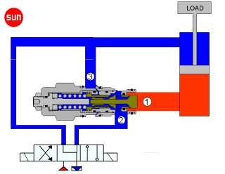
Mount the load control valve as close to the actuator as possible. This will reduce the volume of oil in line 1 and help eliminate the effect of oil compressibility on stability. It will also provide load holding in the event of a hose failure.
Trapped Air Can Cause Instability
Operating cylinders are often at the highest point on a machine and trapped air can accumulate and if the system is not bled correctly the air will simply move up and down when the cylinder is operated.
Under these conditions the method frequently used of cycling the cylinder a few times will not remove the trapped air. A proper bleeding procedure through correctly located bleed points on the cylinders is the only way of removing trapped air.
Cylinder Stick / Slip
Stick slip on cylinder seals can cause instability.
This is a problem which can occur at slow operating speeds with the wrong type of cylinder seals fitted. It can be exaggerated further if the guiding of the actuator is inadequate causing excessive side loading onto the cylinder piston and rod.
Setting Counterbalance Valves
It is always advisable to set the counterbalance valve before it is fitted onto the application but if this is not possible a suggested set up procedure is as follows.
It is critical first to check that the maximum pressure that can be generated by the load is not higher then the maximum setting of the counterbalance valve fitted.
1. Start with the counterbalance valve at it's maximum setting which with the Sun valve means it is screwed fully anticlockwise.
2. Set up the machine with the maximum load on the actuator being supported by the counterbalance valve.
3. Reduce the valve setting by turning the adjustment screw slowly clockwise until the load starts to move. An extended allen-key wrench may be needed because the strong springs in the valve make them difficult to adjust under pressure.
4. Operate the machine to a condition where the counterbalance valve is no longer supporting any load.
5. Turn the adjust screw in fully (clockwise) to the minimum setting, counting the number of turns.
6. Add 30% to the number of turns and then re-set the valve (turn adjustment anti- clockwise) to this setting.
Re-torque the locking nut and fit protective cap if required.
Decompression Shock

Decompression shock can be a problem when piloting open on large flow circuits.