Self-study lesson plans and training record download page.
What hydraulic power units do and where used
Hydraulic power units supply the hydraulic fluid flow, up to the specified pressure, into a system. They should also maintain the fluid at a suitable temperature, cleanliness, and quality level.
The fluid will need to be stored and the temperature remain within a specific range to ensure they operate reliably and the system performs consistently. Maintaining fluid cleanliness is also vital for good reliability, consistent operation. They must also remove any air bubbles that may enter the system by settling them out of the fluid. Air bubbles can often occur through aeration, e.g. being drawn out of solution by low pressures generally created because of high flow restrictions, which is similar to but far more common than cavitation.
Power units generally warn their operator of any problems in the main circuit e.g. loss of fluid, high or low temperatures, filter condition.
Every hydraulic system will require some type of power supply and/or fluid storage and conditioning system. You will find a power unit on every machine.
How hydraulic power units work
Hydraulic power units have a reservoir that holds the hydraulic fluid. This must be large enough to compensate for the cylinder volumes when they extend. It will radiate heat and provide a recirculating time delay to allow the fluid temperature to stabilise. It is common for the reservoir to have baffle plates and a shape suitable for allowing the dirt and air bubble to settle out of the fluid as it passes through.
The power unit will contain a pump and drive system to transmit the fluid around the hydraulic circuit. The reservoir should provide a good pressure head to feeds the pump's inlet port.
An air filter/breather will allow clean to enter the reservoir to compensate for the fluid volume changes as it leaves.
A power unit must have a safety relief valve, otherwise, it could be used incorrectly and risk injury to the operator by generating too much pressure.
Some power units can maintain a better quality of the fluid in terms of temperature and cleanliness. This will be achieved by the use of coolers and heaters to control the temperature and pressure and/or return filters to clean the fluid.
Isolator valves may be provided to increase safety by switching out the unit when it is being maintained. No isolators should be fitted to the return lines although check valves or vent holes may be added to prevent the reservoir draining when components further down the circuit are removed.
Different types of hydraulic power units
Power units come in all shapes and sizes, flow, pressures, colours and complexities. Even their purpose can be different so below we will list the main components you can find while accepting that some units will have all of them and some only a few.
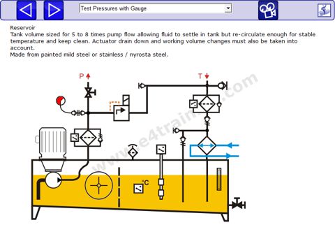
Reservoir
Hydraulic reservoirs come in all shapes, sizes, and materials. They should be sized to allow fluid to settle in the tank but re-circulate enough for stable temperature and keeping the fluid clean by passing enough flow through the filters. They must also be sized to take actuator drain down volumes and accommodate working volume changes without getting too low.
Baffle plate
Reservoir Baffle plates partition the return and supply lines allowing dirt and air to settle before reuse.
Tank access cover
Hydraulic reservoirs require an access cover for cleaning and maintenance purposes. These are typically on the side of the reservoir so users cannot leave them open or use them to poor in the fluid.
Air Breather
Air breathers are always required to compensate for the fluid volume changes e.g. providing a stable pressure above the fluid head. Air entering the reservoir must pass through a filter that is as fine or finer than the main system filters to prevent ingress of dirt. You should not fill a hydraulic system through the air breather but if this is the only way provided new fluid should be pumped in via a separate filling filter.
Suction line
The pump inlet line is a large diameter, short pipe that draws fluid from the reservoir into the pump. Its size is critical for ensuring a low fluid velocity and therefore as positive a head as possible at the pump. Often flexible pipes are used to isolate pump vibration from the tank.
Suction filter
Suction filters can improve supply conditions but they can be dangerous if not regularly checked or maintained, as they can restrict pump supply.
Hydraulic Pump
Fixed or variable displacement pump supply flow to the circuit. Typically gear, vane, or piston design depending on budget and performance. See our pumps section for more details. Pumps are likely to be mounted on rubber mountings to isolate them from the reservoir to reduce noise radiation.
Case drain line
Some pumps require case drain lines which must be adequately sized to keep the case pressures within manufacturers' limits. They also allow the pumps to be primed with fluid before startup.
Bell housing and Coupling
A flexible drive coupling is required between the pump and motor to accommodate any misalignment or vibration. Most pumps cannot accept side loads and some even move slightly with pressure, so rigid location is not permitted.
Electric motor
Electric motors are sized for maximum pump input power, plus a suitable safety margin. Modern, energy efficient designs should be used to reduce overall energy consumption.
Pressure Hose
A short flexible hose is commonly used between the pump and the first component in the circuit. This helps to reduce noise and vibration and allow the pumps to move on their AV mounts.
Pressure test point and gauges
For safety and maintenance, a pressure gauge and/or test points are recommended. These allow operators to quickly check the condition of the power unit and are vital during commissioning and maintenance.
Pressure filter
Contamination causes over 80% of all failures. A pressure filter will reduce the chance of contamination reaching components in the circuit, and if fluid passes through it many times, it should finally stop all contamination from reaching the components. Filters often include a bypass valve so that filters do not get damaged during cold start or near their end of life. A wide range of clogging indicators are available to show when the filter elements need replacing.
Relief valve
Relief valves are essential to protect the system against over pressurisation and potentially dangerous failures. They may also be used to unload the system for pump start-up or standby.
Isolation ball valve
Isolation valves help protect workers during maintenance and stop the fluid syphoning out of the reservoir when items are changed or removed. These valves are often lockable so that people cannot open them and pressurise the system when the maintenance engineer has closed them for maintenance.
Filling point
Filling points should be used to pump new fluid into the reservoir and through the return line filter in order to ensure it is as clean as possible.
Return line filter
Return line filters are used to remove any contamination that has entered the system via cylinder rods etc. Because low-pressure filters cost less than high-pressure filters they are often used as the main cleaning workhorse in the system with the finest filtration rating. Low-pressure return line filters also have a bypass and visual or electrical clogging indicator options that warn when elements need changing.
Anti-syphon valve
Anti-syphon valves are used to stops the backflow of fluid when valves in the circuit are removed for maintenance. Without them it's quite possible just removing one valve will drain all of the fluid from the reservoir overnight.
Sight level gauge
Sight level gauges show the volume of fluid in the reservoir and are good early indicators of problems or leakage. Some level gauges have isolator valves built into them. These are useful because the glass is a potential failure point so isolating the display will ensure you can continue working, even if the glass gets broken.
Level switch
Level switches provide remote, visual, or electrical warnings of low fluid levels and can also have a pump cut-out with very low fluid levels, or warning at high fluid levels.
Temperature switch
Temperature warning and cut-out switches can be provided to ensure the system does not work outside its design limits
Immersion Heaters
Fluid immersion heaters often have built-in thermostats to ensure the fluid stays above its minimum working temperature. This may be required before starting the pumps. Check your operating manuals for details
Cooler
Return line or offline coolers prevent the tank temperature from going above the design limits of the system. These can be a simple inline filter located after the return filters or may be part of a completely separate fluid conditioning circuit that takes fluid out of the reservoir before pumping it back in clean and at the correct temperature.
Further reading
See our Pro course for :
Tips for operating and maintaining power units
Typical power unit operating characteristics
How to specify hydraulic power units
Design Tips, techniques, and potential issues