Total Performance Everytime
Sun HydraulicÂ's load control valves are designed to provide:-
- Smooth and precise actuator position
- Drift-free actuator locking
- Controlled deceleration of loads
- Control of overrunning loads
- Hose break protection
- Protection against thermal expansion
Tighter manufacturing tolerances
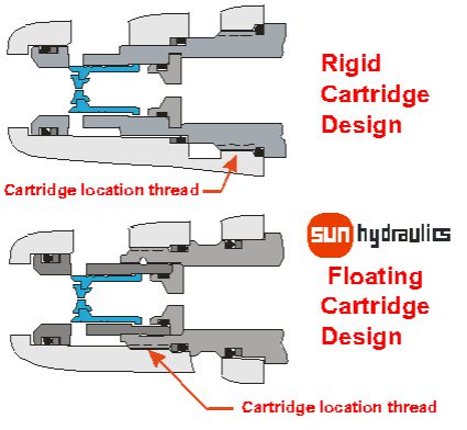
Sun's unique floating cartridge design allows tighter spool machining tolerance to be maintained because it removes the risk of bore distortion due to cartridge installation eccentricities.
Tighter tolerances will ensure better performance, contamination resistance, lower torque sensitivity, reduce wear, improved consistency and a longer working life because there is less tendency for the internal parts to bind.
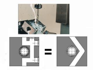
Larger Radial Flow Paths
Sun cartridge body undercuts allow greater flow paths and therefore higher flows, lower pressure drops, fewer cross drilling. This may also remove the need for casting flow chambers, which will also significantly reduce the risk of inbuilt contamination.
Virtual Counterbalance Valve Simulation
Counterbalance application factors.
- How pressures and load effect the valveÂ's performance.
- Effects of varying the pilot ratio.
- Standard and restricted flow versions speed of operation.
- Apply flow control with a counterbalance valve.
- The effects of line lengths and load on system stability.
Reduced Noise Design
Following some recent development work Sun Hydraulics have made significant new advances to their valve's design that has greatly reduced the risk of noise in series 1 counterbalance valves with research now going ahead for other sizes of valve.
These improvements also appear to have provided improvements to the valve's consistency and service life and give the Sun range of products another distinct advantage over the competition.
Undersize rather than oversize
Undersize rather than oversize the valve because the valve is a pressure generating device and a higher pressure drop will create greater system stiffness and help improve stability.
Hydraulic valves control through 'braking' the fluid in much the same way that a car is controlled with its brakes. A smaller valve has more braking potential and will therefore provide better control in the same way that larger brakes on a car provide much better control.
Always use the lowest pilot ratio
Always use the lowest possible standard pilot ratio. High pilot ratios should only be used on very stable motor applications. The added complication of the cylinder area ratio together with a high pilot ratio can often cause stability problems.
A 3:1 pilot ratio means that the spool area acted upon by the pilot pressure is three times larger than the spool area acted upon by the system load. This means that the force generated by the pilot pressure and trying to open the valve is three times more effective than the force generated by the load, which is also trying to open the valve.
A 10:1 pilot ratio means that the force on the spool, generated by the pilot pressure is 10 times higher than the force generated by the same pressure from the system. The result is that with a 10:1 pilot ratio the load starts to move at a lower supply pressure and with a lower pressure drop across the valve. Consequently the 3:1 pilot ratio tends to be more stable and should always be used except in very stable motor circuits.
Benefits of Angled Drillings
Extensive 5 axis construction provides:-
- Better flow paths.
- More compact design.
- Fewer leakage or fatigue points
- Less risk of casting dirt.
- Fewer construction ports.
Counterbalance valves control the load not the speed

It is important to allow the counterbalance valve to control the load and if flow control is also required meter into the actuator not out of the actuator after the valve. Standard counterbalance valves do not like back pressure on them as it will also increase the pilot pressure.
Setting Pressure
The setting specified for a counterbalance valve is always the cracking pressure.
The setting of the valve is always a cracking pressure and should be about 30% above the maximum load pressure. This is because the valve has a hysteresis ( the difference between the reseating pressure to a leakage of less than 5 drops/min and the cracking pressure setting ) of about 85% and it is important that the valve closes fully.