Hydraulic flow control valve symbol
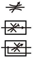
In its basic form, a flow control valve can be just an orifice.
In the top symbol, we see a flow control valve with a variable area adjuster shown by the arrow crossing through it. Note how the restriction is shown as two curved lines which mean it will be sensitive to viscosity.
In the middle symbol, the restrictor is shown as two sharp corners. Sharpe edges indicate a higher quality flow control valve with a higher degree of viscosity independence e.g. more stable flow with temperature changes. The middle symbol also shows a short T-end to the angled line through the orifice which indicates a fixed or pre-set setting rather than a user-adjustable pressure setting.
The bottom symbol shows a third line that the excess flow is diverted into.
Variations in symbol design
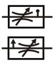
Hydraulic symbols have been harmonised in the ISO 1219 standard but it will take some time for all of the other interpretations to disappear. The symbols that are shown here give an idea of some of the different variations.
The top symbol shows a curved restrictor but the symbol also has a line with a dot that has previously been used to indicate temperature compensation.
The bottom symbol has a side arrow that some manufactures have used to indicate a pressure compensated valve but in ISO 1219 now means a third bypass drain line.
These are earlier versions will no longer be included in the ISO standard and should therefore no longer be used.
Meter-in or out flow control valve symbols
This symbol shows a common form of flow control valve that meters the flow in only one direction only, the flow will go through the check valve in the return direction. The symbol also shows an adjustable orifice, temperature compensated restrictor, and an arrowhead to indicate pressure compensation.
Meter-in is when the flow is controlled going into the actuator and meter-out is when it controls the outgoing flow. Meter-in brings the risk of an uncontrolled cylinder movement, which is very bad, while meter-out risks pressure intensification in the cylinder annulus, which can be protected against in other ways. The general saying is 'if in doubt, meter out'.
The arrowhead along the main flow line shows the valve is pressure compensated. This means that a pressure drop of say 10-20 bar will be maintained across the valve, making it independent of load pressure. Therefore the flow rate will also be independent of load pressure.
The same flow in both directions

This symbol shows how to control the same flow in both directions i.e. with a single flow control restriction. Four check valves are used in a rectifier bridge layout to direct the flow through the same valve, no matter which direction it comes from.
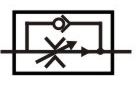
Priority flow control valve symbol

This symbol shows a basic priority flow control valve which is designed to always provide flow to the main priority flow path, up to a pre-set limit, then supply the excess flow to the third line. The straight lines either side of the valve show that it a proportional spool e.g. as the spool moves over the internal orifice opens gradually rather than instantly, as it would in a directional valve. In the one line, there is an orifice. As the flow increases the pressure drop across this orifice increases and acts to move the spool across against the spring. This movement gradually opens the spool, to pass the excess flow into the third line. This type of valve is typically used to always make flow available to a steering system first, but when that has enough flow the remainder is provided to whichever other utility requires it.
Flow divider or combiner valve symbol

The flow divider or flow combiner symbols are one of the easiest to understand. It shows how the flow will be split from one into two lines, in equal quantities by the orifices shown, or combined from two lines into one in equal quantities. However, in reality, flow dividers can be very complex and one of the most troublesome techniques to achieve reliable, repeatable results.
Proportional flow control valve symbol

A proportional flow control valve is one that increases its orifice opening area gradually rather than instantly. These proportional valve symbols show a simple two way, two position spool valve with the proportional spool shown by the two additional lines surrounding the valve element. The first symbol is electrically controlled and the second symbol is controlled by a roller that will be in mechanical contact with another object. The third symbol is a electrically controlled variable orifice device.
Explain the difference between these valves

 What is the main difference between the valves shown in these symbols.