Hydraulic Pipes and Passageway symbols
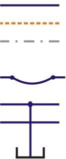
Hydraulic flow lines are shown as single straight lines. This includes both pressure and return lines although different colours may be used to identify this on some circuits.
Pilot flow lines are shown as dashed or dotted lines. Pilot lines generally only transmit pressure feeds or small pilot flows.
Manifold or assembly boundaries are often shown as alternating dashed lines. These identify the physical limit of a group of valves or equipment.
Hoses are shown as an arc with a dot connection at each end.
Where lines crossover nothing is shown but a dot should be used to identify where two or more lines join each other e.g. a physical connection.
A reservoir or point open to atmospheric pressure is shown as a cup symbol.
Ball valves and isolator symbols
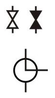
Ball valves or isolator valves are shown as double triangles. When shown in black the valve will be normally closed whereas a clear symbol indicates a normally open valve.
The bottom symbol shows a 3-way ball valve. There are three port connections and two of them are connected as shown in the normal position. There are several variations of this that can be defined by different connection layouts shown by the middle of the symbol.
Hydraulic filter and air breather symbols
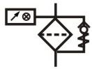
The basic hydraulic filter symbol shows a diagonal box with a dashed line across the flow path. The other elements that make up the larger symbols tell more about what facilities come with each filter.
The top left symbol only has one connection but includes two empty arrows above it. This indicates air moving in and out of the filter elements showing this is an air breather. It's common practice to indicate the filter rating next to the symbol. In this case 5 microns.
The top right symbol is a basic filter element with no other features shown.
The middle left filter has a bypass check valve because the filter element will probably not take the full pressure difference across it. The bypass will make sure the filter only experiences a small pressure difference across the element. The filter also contains a pressure measuring instrument and electrical switch. This is probably a pressure filter as it measures the pressures differential from both sides of the element.
The middle right filter has a bypass check but only has an optical clogging indicator based on the pressure at the supply side of the element. This will reference atmospheric pressure which is fine if it's a return filter with flow feeding straight back into the reservoir. The flow will always enter at the top of these symbols otherwise the bypass check would not work.
The bottom left symbol shows a dual element switchover filter. This arrangement allows one filter element to be changed, without having to stop the production line while the new element is being installed.
The bottom right filter contains an additional magnetic element and has a digital clogging indicator.
Hydraulic fluid cooler symbol
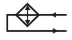
A hydraulic cooler symbol should show the flow of the hydraulic fluid and the flow and type of medium that is being used to take the heat away.
The top symbol shows a basic cooler without indicating the flow path of the coolant.
The middle symbol shows a cooler with liquid coolant, possibly water. The coolant control circuit is not shown in this symbol.
The bottom symbol shows an air blast cooler with electrically driven fan.
Hydraulic accumulator symbols
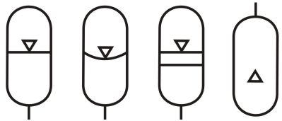
This image shows four symbols for different types of accumulator.
First left is a gas pressurised accumulator with the media separated by a diaphragm.
Second left is a gas pressurised accumulator with the media separated by a bladder.
Third left is a gas pressurised accumulator with the media separated by a piston.
On the right is a gas backup bottle.
What do these symbols represent

 Explain what components these two symbols represent..