Hydraulic flow control valve symbols
Learn about hydraulic flow control valves
Hydraulic flow control valves
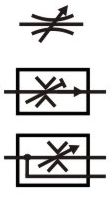
In its basic form a flow control valve can be just and orifice.
In the top symbol we see a flow control valve with a variable area adjuster shown by the cross arrow through it. Note also how the restriction is shown as two curves. In the lower symbol the restrictor is shown as two sharp corners. Sharpe edges indicate a higher quality flow control valve with a higher degree of viscosity independence e.g. more stable flow with temperature changes.
The middle symbol also shows a pressure compensated valve because of the arrow head on the line through the valve. The short T end to the angled line through the orifice indicates a fixed setting rather than an adjustable setting. The third line shows that the excess flow is diverted into a third line.
Variations in symbol design
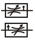
Hydraulic symbols have been harmonised in the ISO1219 standard but it will take some time for all of the other interpretations to disappear. The symbols shown here give an idea of some of the different variations.
The top symbol shows a curved restrictor but the symbol also has a line with a dot that used to indicate temperature compensation.
The bottom symbol has a side arrow which used to indicate a third bypass drain line.
These are earlier versions of that will no longer be included in the ISO standard and should therefore no longer be used.
Meter in or out flow control valves
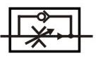
This symbol shows a common form of flow control valve that meters the flow in only one direction only, the flow will go through the check valve in the return direction. The symbol also shows an adjustable orifice, temperature compensated restrictor and an arrow head to indicate pressure compensation.