Understand the different types of relief valve and when and where to specify them.
1-2 What pressure relief valves are used for
All hydraulic power units should have a pressure relief valve somewhere in the circuit, to act as a safety protection device that stops the pressure getting too high if something else in the circuit fails. A common location for these valves is directly after the pump.
Pressure relief valves can provide protection against high external loads acting on actuators that would increase the hydraulic pressure above the equipment's safe working limits.
Where check valves are used in cylinder lines then pressure relief valves can provide protection against thermal expansion of the fluid, which can also cause excessive pressures.
Pressure relief valves are occasionally used to control system or load pressure levels but because this generates heat and is an inefficient use of energy, they are far more common as over-pressure protection devices.
One area where relief valves are used to control pressure levels is within pilot pressure control systems. Here the pilot flows across the relief valves are small but they act on other main spool or logic elements that control the main flow, without such inefficiency.
Another place where you may find a good quality relief valve is controlling the pressure on a test rig.
By adding an electrical solenoid relief valves become electrical unloader valves e.g. as soon as the system registers a fault, or is turned off, the power is removed from the solenoid and the relief valve opens at zero bar.
1-2 How pressure relief valves work
In their simplest form, a pressure relief valve can be a ball bearing held against an orifice by a spring. As the pressure increases the ball is pushed back against the setting of the spring.
Better valves will have hardened seats and shaped poppets to give better pressure vs flow characteristics and more consistent operation throughout their life.
High flow valves tend to have two stages with a small pilot relief valve that opens a larger, second, main stage valve.
Relief valves open when the pressure across them exceeds a pre-set limit. However, if the downstream pressure is acting with the spring then this will change, and therefore the relief valve setting will change. Often multistage relief valves will have external pilot drains or feeds to ensure the signals are stable and reliable.
2 Different types of pressure relief valve
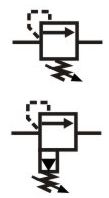
See pressure control valve in our symbols sections for more details.
All relief valves are not the same. Simple ball and spring valves are cheap to produce but will not perform so well. This may not be a problem if it's purely a safety relief valve that should never operate, however, controlling the pressure against different flow rates on a test rig will need a much better standard of valve.
Relief valves options include direct acting, pilot operated 2 stage, electrical unload, electrical proportional, integrated or line mounted versions.
3 Tips for operating and maintaining
Most relief valves work against a spring and have a small Allen key adjuster with locking nut at the end. Always switch the system off before you adjust the setting.
Hydraulic safety relief valves do not need to be removed and recalibrated every year. Risks are more likely to come from contamination getting into the open pipework that the setting drifting. Check the valve in situ, when safe to do so.
The relief valve seats may take a few operations before they bed in from new. It's good to operate them a few time before the first setting.
Equipment often comes with the relief valves backed when delivered, particularly accumulator safety blocks. These will need to be reset carefully during commissioning.
If the relief valve is protecting a load then check the valve leakage to make sure it will not cause uncontrolled lowering of the load. You can simply observe the stationary load to see this.
Consider the effect of the return line pressures on the valve's opening pressure. Operating conditions may be different to the factory assembly conditions so actual pressure relief settings may be different. On mobile equipment particularly, there may also be a part of the valve that is pressure balance with atmosphere. The back of a spring for example. Be very careful that this area does not allow corrosion into the valve. Historically valves had small filters or holes to allow them to vent. Of course, this will still let in moisture and allow valves to corrode, however, it was noticed that many valves had the holes painted over, which protected them from corrosion but also did not stop them working. In response, some modern pressure control design no longer have the vent holes but rely on a sealed air pocket to balance the pressure. While this may work fine it will be tricky to spot any failures if fluid ever leaks into the sealed chambers and upsets the balance.
Always be aware of the setting and interaction of other valves in the system. With working and overpressure tolerances often set around 15 bar, it's possible that venting flow or line pressure drops can reduce this clearance and lead to a valve venting its flow when it's not supposed to.
With some highly dynamic applications, you may need to check that relief valves open quickly enough. Pressure transducers may show overpressure peaks during shock loads.
3-4 Typical operating characteristic
TBC
4 How to specify a relief valve
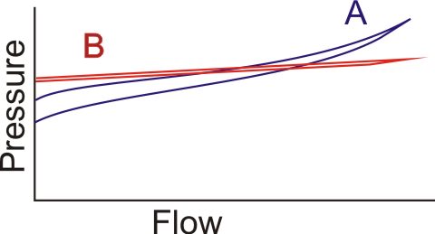
Look at pressure vs flow curves in the supplier's datasheet and select the valve appropriate for your operating conditions. In our example PQ curve you can see that valve A has a low set or cracking pressure but then the pressure rises as the flow increases. As the flow drops there is a large hysteresis gap between the curves and the reset pressure is below the cracking pressure. Valve B shows much better performance with a flat curve and less hysteresis.
Consider the robustness of each valve for use in its environment, with particular regard to how the adjusters will survive in bad weather.
Does the valves operate regularly or only in emergencies. It may need a hard seat to protect against changes in the setting level if it operates continuously.
To protect against shock loads you may need a very fast opening valve, probably direct operated. However, some very fast valves can be unstable if you need quiet, constant pressure level.
Check if you need leak-free sealing or low leakage operation? Direct operated valves can provide this but pilot valves tend to have small leakage paths, which do prevent trapped in pressure but add to the contamination risk.
4 Tips, techniques and potential issues
TBC