Understand where and when directional valves are used. The different options available and how to specify them.
1-2 What directional valves are used for
Directional valves are used to control the movement of hydraulic actuators, primarily cylinders or motors. In their simplest form, this may be a single, hydraulic on/off switch, opening and closing the hydraulic flow to part of the system.
A common format is the 4-way, 3 position valve. These have four ports e.g. a supply and return line plus A and B system port. The valve can switch the flow between the supply port and the A port in one position, the B port in the second position and a final centre, rest position. These valves allow us to connect to the bore and annulus ports of a cylinder and therefore extend and retract a cylinder.
There are many different switching configurations of directional valves. These are arranged to control all type of hydraulic switching requirements.
Example uses include:
Virtually every actuator that does not have a proportional valve, will have a directional valve to control its movement.
1-2 How directional valves work
Directional valves predominantly contain a single sliding spool that moves up and down inside the valve to direct the hydraulic flow along different pipelines. The spools and bores are made to very high tolerances and require specialist machines and skills to maintain the high-quality bore and spool concentricity and straightness, throughout their length.
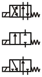
Look at the different directional valve symbols to see which ports they switch from, to or between.
Valves are typically two-way (P to A), three-way (P to A then P to B) or (P to A then A to T) or four-way (P, T, A, B connections)
Valves can also have either two or three positions and are switched between the different positions by either, hand, electrical solenoid, air or hydraulic pilot.
Some valves have springs to return them to their fall-back condition, some have detents that hold them in position until they are reset.
The force required to switch the larger directional valve spools is generally higher than can be achieved by electrical solenoids, so often we will see a smaller hydraulic pilot valve fitted on top of the main spool section, to switch the valve using its internal pilot ports.
2 Different types of valve
There are three main types of directional valves.
Cartridge directional valves that fit into custom manifolds.
Industrial CETOP, plate mounted directional valves.
Mobile, mono-block slice directional valves.
All come in a range of sizes and flows.
Directional valves are either open or closed, there is not in-between, part flow position.
Don't confuse directional valves with proportional valves. Proportional valves provide a measure of flow control depending on how far the spool is moved. Their operation and performance are markedly different.
As with all hydraulic valves, the only way to confidently identify a valve is to make a note of it's full part number and look the number up in the manufacturer's datasheet. There can be a vast number of different design option including:
Spool type, 3 main positions plus switching conditions e.g. as it passes from one condition to the other are the ports linked open, or linked shut. Soft start notches or low leakage design.
Solenoid types, voltage, connector, power-save type.
Material types, seals, body, paint, label.
Two stage valves will also have options around the connection between the two valves.
3 Tips for operating and maintaining directional valves
Tip 1, 2 and 3 has to be, keep your fluid clean. The tight tolerances between the spool and bore mean that small particles of dirt can get trapped between in the gap and lock the spool in one position.
Never leave a valve open to the atmosphere during maintenance. If the valve internals are not fully immersed in fluid their highly machined surfaces can rust very quickly. Always keep sealed in airtight packaging during before assembly or if removed for maintenance. Plug all ports as soon as valves, pipes or hoses are removed.
Always check the full valve code including possible extension numbers at the end of the code. There are many different variants of every manufacturer's standard valves and if you do not get the exact, full code, you may finish up with a replacement valve that does not perform. Typical codes may specify, special seals, different spring forces, low energy solenoids, quiet/soft switching, special materials, low leakage etc. You'll generally have to contact the manufacturer or agent to find out what the codes mean.
Sometimes, CETOP mounted industrial valves have small orifices inserted into their ports between the mounting face. These may be changed during commissioning to achieve the desired performance although circuit drawings may not be updated to show their actual size.
Electrically activated valves have different switching limits depending on their solenoid rating. This means there is a maximum flow rate at which they will switch. Manufacturer datasheets generally provide clear graphs for these limits but because onsite loads, temperatures or fluids may differ from the design specification, it's worth checking that working conditions are not outside the manufacturer's limits.
Don't rely on a spool valve to hold pressure when the supply is turned off. The clearance between the spool and bore will always allow some leakage, which will allow pressure to vent away.
Don't try to re-machine or smooth away burrs. The original tolerances are too fine to consider manual rework.
4 How to specify a directional valve
Select your directional valve based on your application. Mostly it's clear whether it is industrial or mobile etc. but if not, there is probably some similar equipment you can replicate. The main factors will probably be the environment, duty, maintainability, weight or cost. If you are building one machine and you want it to work first time then it's probably a CETOP platen mounted valve, but if you have time for some development then you can probably get a smaller and cheaper design using cartridge technology.
If you are uncertain about what type of directional valve would be best for your conditions then write down all of your environmental conditions and send them to the manufacturer or his agent. I actually recommend doing this on every project whoever you are. We will provide a sample specification in our project planning section.
Look at the component's datasheet to select a valve with the necessary flow rate. Make sure you know how much load your actuator needs under the worse conditions and what pressure loss you will get from the rest of the system. Then select a valve with a low enough pressure drop for your supply pressure. Valve flow ratings can be different for each spool you select.
Check the valves' switching limit. Some valves can lock if you try to put too much flow through them.
Select an appropriate spool centre position. Consider what you want to happen to the load in the standby condition. Do you want its movement to be restricted with an A, B closed spool or free to move with an A, B to Tank spool etc.
Finally, consider the switching conditions. Some datasheets show the spool crossover arrangement as it switches between each of its three main working positions. This can be important if you don't want to lose control of your load as you switch. Also if you have a fixed displacement pump but the valve ports close as it switches, then you'll probably get excessive pressure peaks as it switches.
These days most solenoids are wet pin solenoids. That is the moving part of the solenoid runs in the hydraulic fluid so it is far less likely to seize if the valve is exposed to unfavorable environmental conditions.
4 Design tips, techniques and potential issues
Remember you will always get leakage between the port lands on a spool valve. Some valves more than others. Make sure you cleanly vent unwanted trapped in pressure away. Also be careful that your load does not move due to the leakage when the system is turned off. Although be thankful that spool leakage removes the risk of trapped in pressure exceeding the maximum equipment pressure due to thermal changes. You get a lot less trouble with spool valves than poppet valves.
Be careful that the valve does not need a low tank return line pressure on one port. Pressurising the end caps on some valves is not permitted and risks blowing the ends of the valve off.
Make sure you have a stable reference pressure for switching, this is often the return line pressure which is susceptible to pressure spikes from the main return flow. Because pilot pressure is small compared to the main system pressure, normal changes in the system pressure can be reflected back onto the pilot lines making them unstable and causing the valves to inadvertently switch when not required, or not switch when they are required to.
Harsh operation and noise can be an issue with directional valves. Although you can use flow control valves to reduce the speed, you cannot slow the actuator acceleration with standard directional valves. It's worth calculating the system natural frequency to investigate if proportional valves (see Design Strategies) are required but there are 'soft start' valves switch more slowly and will gradually accelerate the load, therefore working a lot more smoothly and quietly.
3-4 Typical operating characteristics
TBC