Function and operation of a typical circuit
As we discussed earlier a typical hydraulic circuit will contain three main components; an energy source, control valves and an actuator. In this example, we will look more closely at how different control valves may be used within the circuit to control a cylinder movement.
Directional valves control fluid direction
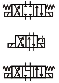
Directional valves (not proportional valves) control the direction of fluid flow. We will discuss the many different versions that are available in later modules but from a fundamental design side, there are no specific formula or hydraulic principles involved.
Flow control valves restrict the speed
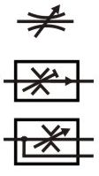
Hydraulic systems generally use restrictors to brake the movement, rather than adjusting the supply flow to control speed. A small orifice or restrictor valve is used to throttle the fluid flow and therefore control the actuator speed.
It may be useful to compare hydraulic control with a motor car, where either the engine throttle or brake pedal can control the speed, but the brake is considerably smaller and cheaper for the same power capacity. It is similar with hydraulics components, the pumps tend to be larger, more expensive and less robust than control valves, so generally, it's preferable and safer to brake the load with a valve rather than control its speed with a pump.
Poppet valves are used to restrict actuator creep
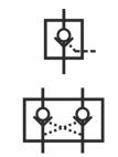
Modern, high-quality hydraulic valves have very tight tolerances. But small spool clearances are still holes and will still allow fluid to leak through and therefore let the actuators creep while systems should be stationary.
Some valves use poppets instead of spools. Poppets generally have very low to practically zero leakage so can be used to seal the flow and hold actuators in position for longer periods.
Example of why hydraulis is used
A major benefit of hydraulic fluid power systems is that the power source can be located remotely from where the power output is required. For example, on a large mobile excavator it may be more efficient to have a cooling fan driven directly from the engine drive shaft, however, this limits the fan location and blade clearance required to compensate for engine vibration. The small loss in system efficiency from using a hydraulic drive is more than compensated for by the increase in overall cooling efficiency. There is rarely space for an electric motor to drive the fan.