Spool Centre Conditions
Experiment with different spool configurations
Mouse over to investigate the circuit conditions
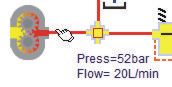
Move the mouse over object or pipes to see the conditions inside.
The flow may show as both positive and negative. This is because the program checks both directions along the pipe and looking in one direction it will be positive and the other direction negative.
Click to operate valves
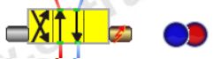
Left click the solenoid (yellow triangle in red box) to operate the valve. The right and left solenoids shift the spool one way or the other.
Note that with the closed centre spool (shown) there will still be a small amount of leakage which is why the flow is not zero and the cylinder creeps slowly in one direction over time.
Set the relief valve pressure
Move the mouse over the relief valve to see the flow and pressure setting. It may be that the relief valve setting is higher than the pressure level in the circuit. In this case the program may display both values, switching continuously between the two. This is quite normal as the circuit is telling the valve at what pressure it is working and the valve telling the circuit at what pressure it is set.
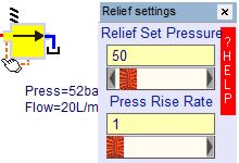
Hold the mouse over the relief valve for a few seconds (or right click in download version) to open the valve data window.
Set the relief valve cracking pressure in the top edit box. Either type in the number, adjust the slide bar or click on the slide bar arrows to set the pressure you require.
The pressure rise rate, set in the lower box, covers the rate at which the pressure increases with increasing flow. Look at the component data sheet for the valve you will be using and there should be a graph from which you can estimate the appropriate value.
Set the directional valve performance
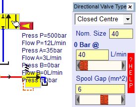
Move the mouse over the directional valve to display pressure and flow at each port.
Hold the mouse over the directional valve (or right click in download version) to display the settings window.
Select the spool centre condition from the drop down list box.
Enter the nominal bore size in the second edit box. You can adjust the flow slide bar to see a typical pressure drop across the valve. Usually valve datasheets have typical flow vs pressure drop curves for each spool so you can adjust the nominal size to give the most appropriate curve.
The spool gap allows you to add a figure for the spool clearance or leakage when closed.
Cylinder dimensions
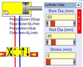
Change the cylinder bore, rod size and stroke using the cylinder data window.
External loads on the cylinder
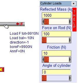
You can add three different types of load onto the cylinder.
The top box is for the reflected mass. This is simply the mass in kg that the cylinder will move. However, if the mass is on the cylinder is driven through a mechanical linkage you will need to adjust this by the square of the radius to give the reflected mass.
Alternately the load may be in the form of a constant force rather than one generated by a mass. The force is assumed to act onto the rod and should be negative if acting away from the rod.
A friction force will always act against the movement of the cylinder. Typically this might be equivalent to 3 to 5 bar of cylinder pressure.
The cylinder angle is important to calculate the load from the mass and is measure in an anticlockwise direction. Zero degrees is horizontal, 90 degrees is with the mass acting down onto an upwards rod. A horizontal cylinder would not apply a static load to the cylinder but the mass would still be important in calculating the system natural frequency.
Comparing spool centre conditions
Different spool centre configurations would be used depending on the type of load and pump that are being used.
Operate the directional valve until the cylinder lies around the middle of its stroke.
Change the spool centre condition from the drop down box in the directional valve data window.
Watch what happens to the cylinder, pressures and flows. With certain spool designs the simulation may not be stable, however, an hydraulic circuit with the same design would also not be stable.
Select the spool type you consider to be most appropriate for the circuit.
The correct answer is that you can't say which is correct until you define what the system is doing although it's unlikely you'd want the pump continuously on load.
Load new circuits or save your changes
Load new example circuits with the load button.
Move components or change their properties then save the circuit with the save button.
Print a graph of the results
Drag a printer icon onto the components you want to plot a graph of.
Press the print button every time you wish to take a new reading.
Copy the results into a spreadsheet to produce a graph and print them out.