Ancillary hydraulic equipment symbols

Symbols for pipes, ball valves and ancillary valves etc

Hydraulic Pipes and Passageways

Hydraulic pipe symbols

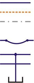
Hydraulic flow lines are shown as single straight lines. This includes both pressure and return lines although different colours may be used to identify this on some circuits.

Pilot flow lines are shown as dashed or dotted lines. Pilot lines generally only transmit pressure feeds or small pilot flows.

Manifold or assembly boundaries are often shown as alternating dashed lines. These identify the physical limit of a group of valves or equipment.

Hoses are shown as an arc with a dot connection at each end.

Where lines crossover nothing is shown but a dot should be used to identify where two or more lines join each other e.g. a physical connection.

A reservoir or point open to atmospheric pressure is shown as a cup symbol.

Ball valves and isolators

isolator valve symbol

Ball valves or isolator valves are shown as double triangles. When shown in black the valve will be normally closed whereas a clear symbol indicates a normally open valve.

The bottom symbol shows a 3-way ball valve. There are three port connections and two of them are connected as shown in the normal position. There are several variations of this that can be defined by different connection layouts shown by the middle of the symbol.

Shuttle valve

shuttle valve symbol

Shuttle valves are most common on load sensing systems. They are designed to always feed the highest pressure to the top connection. The symbol clearly shows that if two different pressures are fed onto the bottom lines then the ball will move either way to allow the maximum pressure onto the top connection.

Learn more about shuttle valves


Page 2 of 10 / Next Page