External gear pumps
Learn how gear pumps work
Understand where and why gear pumps are used and how to install and maintain them
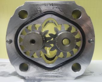
External gear pump design details
The majority of gear pumps have an aluminium body and two end plates. The drive and driven gear are assembled inside the bearing blocks and float slightly within the body cavity. With high pressure on one side of the gears the floating gear and bearing assembly, used in most gear pumps, are forced back against the inlet side of the pump body, therefore, giving very low clearance between the rotating gears and the pump body; this helps give the high volumetric efficiency of the design. In fact, during manufacture, all pumps are run at their maximum pressure in a controlled manor and the gears cut into the body to producing the optimum clearance tolerances. For this reason, gear pumps should not be subjected to pressures higher than their rated pressures as they will then cut further into their bodies and create unwanted contamination and reduced efficiency.
Seals within the ends of the floating bearings are shaped to push the bearings against the side of the gear faces thus reducing clearances and increasing efficiency.
How external gear pumps work
The gears rotate inside the body carrying fluid around the outside of the gears. The fluid cannot return through the centre of the meshing gears so is forced out through the pressure port.
Tandem gear pumps
Multiple gear pumps can be driven from one drive by piggy backing the drive gear of all the pumps.
Installation issues
Keep the reservoir above the pump suction where possible.
External gear pumps will generate light suction on the inlet side of the pump. NEVER start the pumps dry; they will not draw fluid when dry and will quickly fail. Prime the pump with fluid before you start them for the first time and ensure the do not drain down if they have a negative head.
Noise levels
Standard gear pumps generate high-pressure ripples and therefore hydraulic noise.
As the teeth mesh, they exhaust the fluid in a characteristic flow ripple dependent on the form of the gear face. Any machining errors or tolerances on the gear face can also manifest themselves in the fluid as noise.
The amplitude of the pump ripple is dependent on the number of teeth on each gear. More teeth will give more ripples of lower amplitude. Although dependent on the resonant frequency of the machine this will generally reduce the noise level generated by the equipment although it will be at a higher and possibly more annoying frequency.
Pump manufacturers often provide quiet versions of external gear pumps based on one of the following approaches.
Phased gears providing 2 times 12 teeth.
Zero backlash design where teeth act individually rather than in pairs.
Modified gear form pumps. Gears shapes are designed for constant speed transmission drives but in gear pumps, this is not important so the form shape can be modified to vary the speed of the second gear and therefore balance out the uneven flow ripple.