Understand pressure relief valve design features, specification and performance limits
Self-study lesson plans and training record download page.
3 Tips for operating and maintaining
Most relief valves work against a spring and have a small Allen key adjuster with locking nut at the end. For your personal safety you must always switch the system off before adjusting the setting.
The relief valve seats may take a few operations before they bed in from new. It's good to operate them a few time before the first setting.
To set or test a safety relief valve it is probably necessary to operate above the working pressure of the equipment. This may not be possible within the normal operation of the environment and clearly raises a number of safety issues that must be addressed. In general, you should not need to remove and recalibrate a safety relief valve every year. Risks are more likely to come from contamination getting into the open pipework that the risk setting drifting. If a valve has to be reset then it's always better to remove it and reset it on a test rig, however, it can sometimes be practical to calibrate the number of turns to increase the valve by say 15 bar, then raise its pressure to the maximum working pressure and add this extra turn angle. Complete a risk assessment beforehand and change the valve in situ, only when safe to do so.
Equipment sometimes comes with the relief valves backed off before delivery. These will need to be reset carefully during commissioning.
If the relief valve is protecting a load then check the valve leakage to make sure it will not cause uncontrolled lowering of the load. You can simply observe the stationary load over time to see this.
Consider the effect of the return line pressures on the valve's opening pressure. Operating conditions may be different to the factory assembly conditions so actual pressure relief valve settings may be different. On mobile equipment particularly, there may also be a part of the valve that is pressure balanced to the atmosphere. The back of a spring for example. Be very careful that this area does not allow corrosion into the valve. Historically valves had small filters or holes to allow them to vent. Of course, this will still let in moisture and allow valves to corrode, however, it was noticed that many valves had the holes painted over, which protected them from corrosion but also did not stop them working. In response, some modern pressure control design no longer have the vent holes but rely on a sealed air pocket to balance the pressure. While this may work fine it will be tricky to spot any failures if fluid ever leaks into the sealed chambers and upsets the balance.
Always be aware of the setting and interaction of other valves in the system. With working and overpressure tolerances often set around 15 bar, it's possible that venting flows or line pressure drops can reduce this clearance and lead to a valve venting its flow when it's not supposed to.
With some highly dynamic applications, you may need to check that relief valves open quickly enough. Pressure transducers may show overpressure peaks during shock loads.
3-4 Design features and operating characteristics
To fully understand a valve's operating characteristics you must to be able to analyse the design features within each valve. The same features appear over and again in all hydraulic valves and we've already provided a review of some key design areas in the check valve section here. These features include:-
- Poppet nose shape affecting the flow characteristic when new and worn.
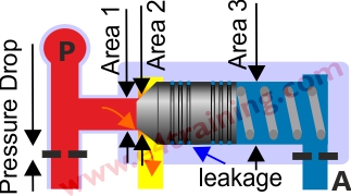
- Flow limits based on opening sizes and pressure area differences.
- Nose to bore concentricity affects e.g. spool vs poppet effects on leakage.
- Limiting contamination silting risk factors.
- Speed of response and dynamic performance effects.
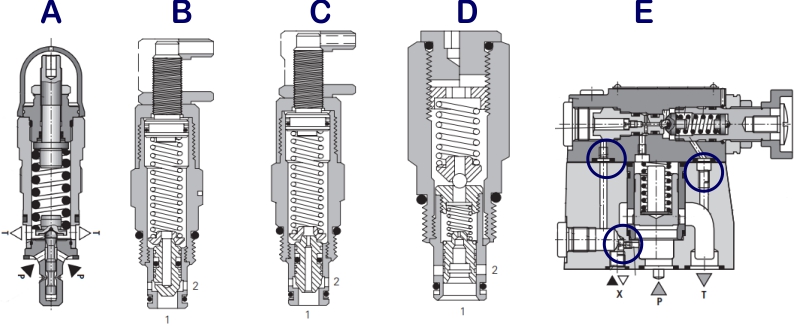
Valves A, B and C in the diagram show direct-acting relief valves. Valves A and B have significantly different poppet designs including area ratio, damping and nose shape. Performance curves will also be different. Valve C is a differential area valve where the higher pressure is applied to port 2 and the low pressure is applied to port 1 and the back of the poppet.
Valves D and E are pilot operated valves, D is a cartridge valve and E platen mounted valve. Valve E has a positive, sharp edged nose closure seat. This will give less leakage, better contamination resistance and an improved PQ (Pressure vs Flow) characteristic. Valve E also has a number of passageways where pilot feeds can be taken from different sources or small orifices added to control the dynamic performance, although opening times are always likely to be slower than with direct operated valves.
Direct operated relief valves
Direct operated valves tend to have small poppets or balls and therefore are used for smaller flow applications. Their advantage is their fast opening response time and low or leak-free operation. They tend to be used where intermittent, fast response is required.
Direct operated valves don't tend to have pilot drain connections so will be sensitive to return line pressures acting on the back of the poppet. However, they are often used as pilot valves to larger relief main-stage valves, in which case their low flows can be feed straight back into pilot drain lines, making them independent of return line changes.
Differential area direct operated relief valves
Due to their larger flow paths, differential area valves might be used in situations where higher flows and lower pressure rise rates are required. They can also be less sensitive to pressure spikes.
By exposing both the nose and spool element to silting they can bring an increased risk of contamination and are unlikely to provide the flow capacity of a pilot operated valve.
Pilot operated relief valves
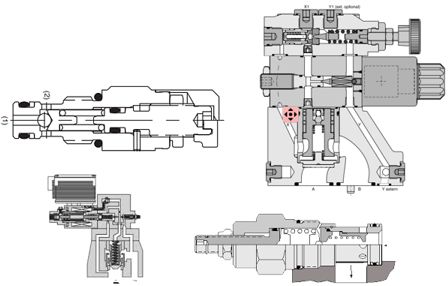 Having a two-stage valve will make response times longer but the much larger size of the main stage section will allow higher flow rates with flatter pressure rise rates. The big issue with a two-stage valve is that the second stage will be a spool element which has a small clearance that will allow fluid to leak through. This means that, unlike a direct operated valve with a low leakage poppet, the spool section means it can never be used for a load holding function as the cylinder would always drop too quickly.
One big advantage with pilot operated valves is that the pilot feed drain can be configured to create a range of different functions e.g. electrical unload, remote pilot feed from an external valve or remote pilot drain to stable pressure. These feed lines can also be damped with different orifice sizes to control the valve response times.
Cracking Pressure
Cracking pressure is defined as the pressure at which the valve first starts to open. Immediately the valve opens the flow will move down the nose of the poppet and this will change the pressure area. The effect will probably be to increase the opening pressure area although if the valve is badly worn, or designed, the flow forces can create negative pressures on the spool which can create distortions in the PQ curve or even instability.
PQ (pressure vs flow) curve
As the valve opens the flow through the seat diameter or spool restrictions will increase. This will lead to an increase in the effective opening pressure as the flow increases. This is commonly known as the pressure rise rate and is why we should always look at the PQ curve when selecting the appropriate valve.
Operating curve hysteresis
As the flow through a valve increases the pressure at valve entry also increases. As the flow decreases the pressure will not follow exactly the same curve and can sometimes show a marked difference between the pressure levels for the same flow. This difference is known as valve hysteresis and is generally worse in direct operated valves, lower cost cartridge valves and valves with dynamic seals.
Reseat pressures
Valves will close at a different pressure to what they open. This pressure difference can be significant and potentially lead to situations where pressure control valves stay open and stop other components working properly. It is another effect of hysteresis and less of an issue with better quality valves or with good clearances between system pressure settings (approx. 15 bar)
4 How to specify a pressure relief valve
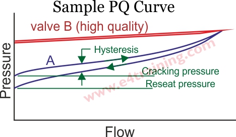
Look at PQ (pressure vs flow) curves in the supplier's datasheet and select the valve appropriate for your maximum flow rate. In our example PQ curve, you can see that valve A has a low set or cracking pressure but then the pressure rises as the flow increases. As the flow drops there is a large hysteresis gap between the curves and the reset pressure is below the cracking pressure. Valve B shows much better performance with a flat curve and less hysteresis. You will need to set the cracking pressure above maximum working pressure but make sure that the pressure rise rate does not permit the actual pressure to exceed the settings or maximum pressure rating of other components.
Consider the robustness of each valve for use in its environment, with particular regard to how the adjusters will survive in bad weather.
Does the valves operate regularly or only in emergencies. It may need a hard seat to protect against changes in the setting level if it operates continuously. Whereas a lower cost, combined body with seat may be appropriate if the relief valve will only operate as a last resort safety device.
To protect against shock loads you may need a very fast opening valve, probably direct operated. However, some very fast valves can be unstable if you need quiet, constant pressure level. Manufacturers often have valves with different dynamic performances that don't appear in their general datasheets.
Check if you need leak-free sealing or low leakage operation? Direct operated valves can provide this but pilot valves tend to have small leakage paths, which do prevent 'trapped in' pressure but can add to the contamination risk.
Accumulator safety block relief valves will require certification.
4 Design Tips, techniques and potential issues
Key design features have been covered in the check valve training section. These factors also apply to relief valves.
We recommend that users pay particular attention to the number of machined surfaces that need to be concentric to allow the poppet to sit cleanly on its seat. A ball bearing, for example will seat cleanly on its seat, but when poppets a machined to slide in spools then these must be made concentric with the valve seat. This will probably be more difficult for the supplier to achieve when machined into a cartridge body, which is why the higher quality valves have separate, hardened metal inserts, into which the poppets slide and seal.