Self-study lesson plans and training record download page.
Unwanted pressure peaks
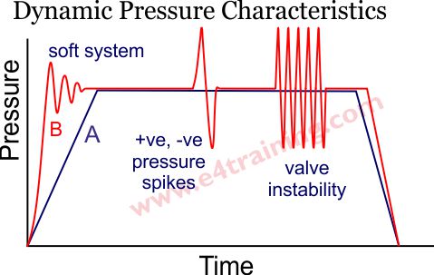
If you record the system pressure with an electronic pressure transducer you may well see a very dynamic reading with lots of pressure peaks or oscillations. These pressure peaks may also be noticeable as general noise or judders and besides being detrimental to the control, they will damage components and reduce the operating life of the equipment.
The oscillations are caused due to the system dynamics and interactions between the machine loads and hydraulic components. The following sections will look more closely at the main causes of these pressure peaks and offer potential solutions for removing them. With good circuit design and component selection, you should be able to eliminate any peaks that pose a concern.
Cause 1 - Steady-state vs dynamic load
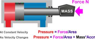
Under steady-state conditions with a constant velocity, we should see a nice stable pressure trace. However, when starting and stopping the movement we will have to accelerate or decelerate the load mass, and this change of state will result in additional pressure being generated within the hydraulic system to overcome the extra force required.
Under steady-state conditions, the pressure simply equals the force divided by the area.
Under dynamic conditions, as the load accelerates, the pressure equals the force/area plus the mass time the acceleration of the load.
Cause 2 - Mechanical and hydraulic natural frequencies
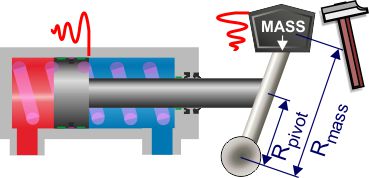
Steel and fluid are not incompressible, just very stiff. When moving them very quickly or hitting them with a large hammer, they will oscillate at their system natural frequencies and these frequencies will show up in the fluid as a pressure ripple.
These system natural frequencies can be calculated and measured and this should have been done for all proportional and servo system designs. Use our valve and cylinder system design guide to calculate your natural frequencies.
Cause 3 - Valve internal dynamics
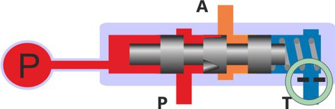
Every hydraulic valve is a unique hydro-mechanical system. As such, each valve will have its own unique dynamic performance and natural frequency. In perhaps 90% of well-designed applications this will not matter, however, there can be situations where the loads, temperatures, performance, or other system dynamics interact with particular valves which result in pressure peaks or oscillations.
Cause 4 - Shock loads onto the system
Pressure peaks can result from impacts or shock loads onto the hydraulic actuators and not result from anything to do with the hydraulic system or component design.
Solution 1- Cylinder cushion stops
If the cylinders in your application are simply run against the cylinder ends to stop then the deceleration forces will pass directly into the mechanical system as noise or judder. A simple solution to this is to include cushions within the cylinders to gradually decelerate the load before it hits the end stop.
Solution 2- Soft-start valve opening
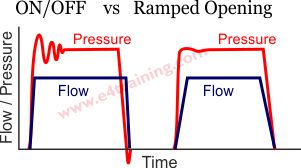
This image compares the flow rate and pressure ripple from an instantaneous and gradual or ramped opening valve.
In a simple on/off valve, the flow rate can switch from zero to full flow almost instantaneously and the corresponding acceleration of the mass can generate the pressure ripple shown.
With a ramped valve opening we slow the rate at which the flow increases and therefore accelerate the load more slowly. The optimum rate of acceleration can be calculated from the system natural frequency although it is sometimes easier and more effective to test changes when issues occur. Slowing the load acceleration by only small fractions of a second can often be enough to remove the unwanted pressure spikes.
There are several different ways to slowly accelerate a load. All of these solutions have only limited control of the ramp time changes so may only work in certain situations. On/off directional valves can include a proportional style notched spool along with a damped opening speed which will result in a gradual flow rate increase through the valve. Soft-start relief valves and soft-start solenoids are available to slow down the pressure supply or valve movement. Including flexible hoses or accumulators into the pipework will slow the pressure rise rate either fractionally with a hose or in a controlled manner with an accumulator.
Solution 3- Proportional valve ramped opening
In applications where control is important or cylinders need to be stopped and started accurately, in mid-stroke, then proportional control valves will be required. One of the key features of these valves is that they can be opened gradually by an adjustable electrical signal. This means that the opening speed can be optimised for each circuit natural frequency so we can achieve the quickest cycle time with the minimum of oscillation.
Solution 4 - Natural frequency changes
There are two or three important natural frequency factors in every circuit. The rigidity of the mechanical system, the compliance of the hydraulic circuit between the cylinder and the valve and sometimes the dynamic operating speed of the valve itself.
In most simple hydraulic systems the way cylinders are sized means that the circuit natural frequencies typically fall around 10 Hz, which is quite suitable for good, stable operation. Job done!
In a few applications with long, thin cylinders the natural frequency can drop near our 3-4 Hz minimum limit. These need to be treated carefully and almost certainly need ramped, proportional control.
For high-performance systems the mechanical stiffness, pipes, cylinders, and potentially even the valve will need to be carefully designed to meet the minimum overall natural frequency required to achieve the dynamic performance specified. We cover more about this in our proportional and servo valve section.
Solution 5 - Valve dynamic changes
Every valve is constructed from a number of small spool masses, fluid cavities, springs, and orifices. This makes each valve a small hydro-dynamic system in its own right and there is always the chance that different valves will interact or perform differently in the same application.
Hydraulic engineers always advise that pressure control valve setting remain 10-15 bar apart to avoid interactions.
Typically direct-acting valves tend to be fast and potentially unstable with pilot-operated valves responding more slowly but able to hold a more stable control. Internal orifices can sometimes be changed to control the dynamics of individual valves and although manufacturer datasheets only list a small number of valves, they often have additional valves with modified dynamics within their manufacturing catalogue.
Solution 6 - Closed-loop control
Closed-loop control is when a signal from the sensor on the load is fed back into the control system to calculate what drive force should be given to the valve to move the load to where it needs to be. This solution allows engineers to specify different type of Proportional, Integral or Differential (PID) control to provide the optimum load performance.