Self-study lesson plans and training record download page.
Pilot control systems
This module discusses the use of hydraulic pilots supplies and feeds for controlling hydraulic systems. We cover the background and reasons behind why pilot pressure control is used along with discussing the types of application in which it is used.
What is a pilot control system
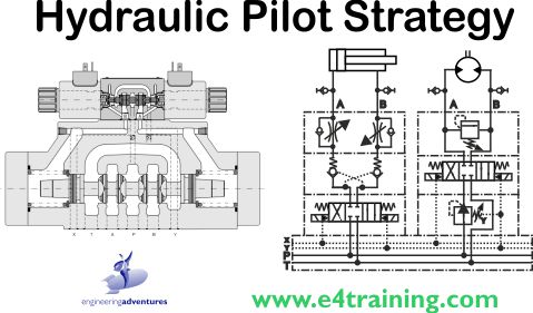
It is common in hydraulics to use a smaller 'pilot' valve to control a larger 'main stage' valve. Hydraulic directional valves over CETOP 5 are generally all fitted with pilot valves, as shown in our example.
How pilot control works
The forces required to move the larger spool in the main valve are significantly higher than the small pilot valve. This means they need larger spring and would need much larger solenoids. By using a small hydraulic valve to supply the flow to the end of the main stage spool, we can still use a small, standard, solenoid size but have more than enough power to switch it and also the ability to add extra controls such as pressure regulation or time delays.
Different types of pilot pressure control
Pilot pressure systems are used in a number of different ways and with a number of different approaches.
The simplest is probably as shown above with a small directional valve controlling a larger directional valve. We've also seen in the pressure relief valve training module that many relief valves have small pilot relief valve working over their main pressure control stage.
With mobile control blocks, we often see the main spools controlled by small electro-hydraulic proportional pressure reducing valves. These control the pressure against each end of the spool and therefore move the spool against their springs, proportional to the pressure they apply.
Pressure control valve vents
As we have discussed in our load control strategies module, pressure control valves always need a stable reference pressure to work against. If we have valves sitting right on a cylinder and it only sees the A and B line pressures then it can only be set at say 30 bar plus what the cylinder line pressure is. And this is unlikely to be zero if proportional or meter out controls are used.
In these cases, we should add a pilot drain line to provide the zero pressure reference from the tank. However, to save money many manufacturers use vent to atmosphere valves that provide this zero reference from the air around the valve. This is fine in theory although in practice we now have an open vent, often in the rain and dirt of an excavator's arm, which can let water and air into our nice clean fluid system and sometimes even allow the ends of our moving parts to rust. To prevent dirt ingress valve manufacturers started to add small filters inside the valve end caps instead of just a small hole. This approach worked surprisingly well and was interesting because people realised that these filters were being regularly painted over so there was no air gap at all, and no chance for dirt or water to get in. Because this worked we now see a new range of vent to atmosphere valves with a rubber seal over the vent hole. The theory now is that the air inside the chamber provided the zero reference and any changes as the valve spool and volume change are not significant because air is compressible. This should be fine until a valve seal starts to leak into this trapped air volume and the valve function starts to change. This may be solved by a simple valve change but identifying the fault could be difficult.
Pilot pressure drain systems
Pilot pressure control systems are often used to ensure better control, particularly with high performance proportional and servo control systems. They achieve this by making sure the control valves have a consistent supply and drain pressure to them. It's not just the variation in nominal pressures that are a concern but more the peak pressure spikes that occur. For example, if you cylinder quickly you may get spikes in the pressure and return lines as the movement starts and stops as well as marked changes in the return pipework as the flow returns to the tank. These peaks and troughs are also likely to appear when other actuators move, not just the one we are controlling.
To prevent these main line pressure spikes being fed back into the control valves and affect the machine we are controlling we can use separate feed and drain lines. Their use will depend on the particular application but adding a separate pilot drain line is quite common as it is generally not too expensive and because it will be much more stable, it should remove much of the risk of poor control.
Pilot pressure supply systems
To remove all risk of interactions between the systems actuators and the pilot control valves we can add a separate pilot oil supply.
These have a separate, stable pressure feed to the pilot valves that is separate from the main supply flow. This is because the main pressure is likely to fluctuate depending on what its consumers are doing. It may also require a different pressure level to the pilot valves.
Pilot pressure supplies may be taken straight from the main fluid supply via a pressure reducing valve to give them a separate, stable pressure. Alternately they may have a completely different pump and filter system supplying them.
Tips and trips about pilot valves
Just because the system has a separate pilot oil supply or drain, don't assume this will not have pressure fluctuations itself. Some valves, particularly reducing and relieving valves, can have surprising high drain flows. These in themselves can upset pilot drain pressures and should be checked.