Self-study lesson plans and training record download page.
Learn the hydraulic fundamentals
The great thing about hydraulics is that you don't have to remember lots of complicated formulas to understand how things work. If you learn the basic principles shown in the following paragraphs, you can apply them to almost every other valve to understand how it works.
Hydraulic valves all use the same basic piston, spring, and orifices but in slightly different ways.
Piston force compresses spring
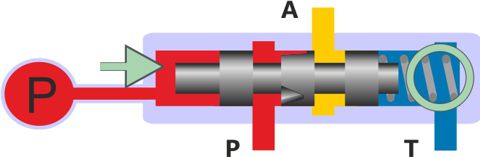
Spool displacement is controlled by the pressure on one end of the spool working against the spring force on the other. As pressure increases the spring compresses and the spool moves.
Orifice size controls pressure or flow
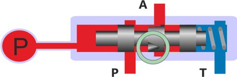
With a constant pressure at port P, the flow rate will be controlled by the size of the orifice.
With a constant flow at port P, the size of the orifice will give a fixed pressure drop which will control the pressure upstream of the orifice.
In the valve diagram shown the orifice size is controlled by the displacement of the spool opening or closing the triangular notch in the spool between ports P and A.
Displaced fluid controls speed
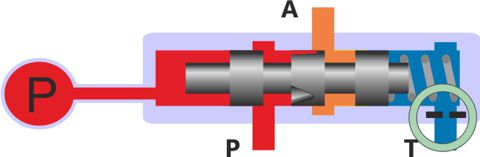
Valve dynamics are controlled by orifice restrictions within the design. In the valve shown the spool movement is delayed by how long it takes for the fluid volume held within an end chamber to flow through an orifice at the T port.
Smaller valves are often used to control the pilot flows of larger valves. Sometimes valves need to move very quickly to give a fast response while other times valve switching speeds may need to be slowed down to provide more stable operation.
Leakage vs trapped in pressure
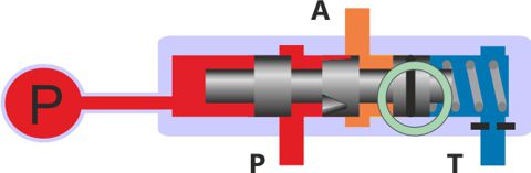
Some fluid leakage will always occur through the clearances around the outside of a spool. It's this feature that means no metal touches and therefore hydraulic equipment takes such high power densities and duties for such long periods.
Leakage may reduce overall efficiencies but it does protect against trapped in pressures. Care must be taken to consider standby and switching conditions. For example, if port A is a sealed pipe then its pressure will always be a ratio of the P and T pressure based on the leakage across each land. Designs generally try to be either one or the other.
The spool shown includes an O ring seal on one land. This will stop leakage but will also affect the characteristic and hysteresis of the spool.
Poppets make physical contact with the seat and while you can never guarantee a 100% seal, poppets often do trap in pressure which creates the risk of extreme pressure caused by temperature changes. Every 15C rise will generate a 70bar increase in pressure.
Hydrodynamic flow effects
Whenever the flow changes direction or passes through a different flow area, its local pressure will change. These pressure changes can have a significant effect on the spool or poppet pressure balance and therefore set position. Often significant work is carried out by valve manufacturers to limit the effect of flow forces within their valves.
The shape of a valves Pressure Vs Flow (PQ) characteristic provides a good comparison of the quality of the valve. You should also check the hysteresis, cracking pressures, resolution etc.