Based on ISO 1219-1 and 2
2 way 2 position directional valves
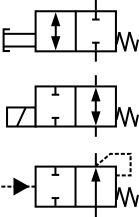
The valves shown are all two way, two position directional valves. This means they have two flow pipe connections and can switch into two different positions.
The top symbol shows a manually activated valve that is pushed over against a spring. The double arrow in the left box shows that the flow may pass in both directions. Valves should always be drawn in the de-activated position e.g. pushed over by the spring, not the solenoid. This top valve, therefore, shows a 'Normally Closed' (NC) valve e.g. in its standby condition, the right-hand box is connected to the pipes and no flow can pass through (closed). When activated the left-hand box would be connected to the pipes and flow could pass through the valve.
The middle symbol shows an electrically operated valve which is 'Normally Open' (NO).
The bottom symbol shows a hydraulically operated valve, but in this case, flow can only pass in one direction because the spring chamber is connected to the low pressure, return line connection. When using valves that switch pressure lines, without a direct, low pressure, return line connection it is important to make sure that the valves solenoid and spring chambers are rated for the maximum pressure they may see. Not all valves will operate or work safely without a low-pressure drain signal.
3-way directional valves
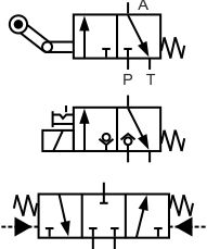
The valves shown are all three-way valves. This means they have three flow pipe connections.
The top symbol shows a two-position valve that is switched by a mechanical roller. An example might be that as the cylinder extends, it contacts the roller, which switches the valve and this stops the cylinder stops moving.
The middle valve also has two positions but it is operated by a solenoid and includes a detented hand emergency button. The ball on seat symbols inside the valve also indicates that this is a low leakage poppet style valve rather than a traditional spool style valve.
The bottom symbol shows a three-way three position valve that is hydraulically operated. This valve also has two end springs to return the spool to the centre position when no pilot signal is available. Note how the hydraulic pilot is shown as a solid triangle although if this was a pneumatic pilot it would be shown as a clear triangle.
4 way 2 position directional valves
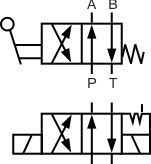
Both valves shown are four-way two position valves. The '4 way' means it has 4 pipe connections, generally Pressure, Return, Port A and Port B. The 'two position' means that it has two switched positions i.e. it can sit in the A or B position.
The top valve is operated by a manual lever and includes spring return.
The bottom valve is solenoid operated with two detent positions to hold the valve in its last switched position.
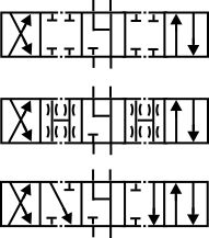
4 way 3 position directional valves
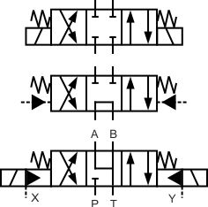
All symbols show four-way three position valves. They are all shown at standby in their centre positions. Note how the valves all have two springs so that with no signal to the valve, it will sit in its central, standby position.
When the electrical solenoids are operated the spool position moves to either the right or left-hand position, allowing the different symbol logic to be employed.
The top symbol shows a direct operated (single stage) directional valve with all ports blocked in the centre position. However, because this is a spool valve there will be some leakage between ports so the A and B lines may still be subject to experiencing different pressures and facilitating cylinder creep.
The middle symbol shows a hydraulically operated valve with an open P to T line. This format is commonly used with fixed displacement pumps so that there is no pressure on the pump when it is not required.
The bottom symbol shows a two-stage electrically operated valve. The A, B and T lines are connected together in the centre position to avoid pressure build-up on the actuator. This valve also has a remote pilot feed to the solenoids at X e.g. a stable 100bar perhaps. And an external pilot drain at Y, so that line pressure variations aren't felt by the solenoids.
Directional valve switching conditions
 What does it mean if the valve is shown with 5 sections.
Sometimes it is vital to know whether a particular flow line will remain open or shut while the valve is switched. For example, if you are using a fixed displacement pump and you switch the direction of flow from P to A to P to B, and during this changeover the P port is blocked, then you will probably see a very high-pressure spike that is likely to instantly damage the pump. But if you select a valve spool that remains open P, A, and B to T during switchover, then no damaging high pressures will occur. However, this configuration could be very dangerous if stopping the load from falling is the main concern.
These symbols show a range of crossover conditions for the same style of 4 way 3 position valve. The fourth and fifth positions are purely what happens at the point at which the valve switches.