Learn about the components you will find in a simple hydraulic circuit.
Self-study lesson plans and training record download page.
Function and operation of a typical circuit
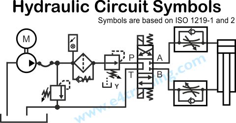
The function of every hydraulic circuit can be described by a language of individual component symbols that are combined together to explain how the circuit works. They should conform to the Internation Standard ISO 1219 parts 1 and 2. This following section will look at some common symbols for the components used in our basic circuit. More detailed information on a wider range of components can be found in our symbols section.
Hydraulic Pumps
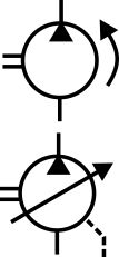
Hydraulic pumps are a circle with an arrow showing the direction of flow.
The top pump is fixed displacement but the arrow across the bottom pump shows it is variable displacement and has a third, case leakage line.
Directional control valves
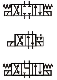
Directional valves control the direction of fluid flow. They may be operated a number of different ways including electrically, manually, or mechanically. They may also switch between 2 to 4 different pipelines and come with many different switching connection options. We will discuss the many different versions that are available in later modules but from a fundamental design side, they are either open or shut and simply change the pipework connections.
Directional valves are normally constructed using a spool that moves up and down a very high tolerance bore. Even though spool to bore clearances are very small there will still be some leakage over time, which will allow heavy loads to creep, if they are not isolated.
Pressure control valves
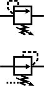
Pressure control valves are used to set the pressure level within a circuit or limit the maximum pressure.
The top pressure relief valve will relieve the pressure upstream of the valve when it exceeds the valve's setting.
The lower valve will reduce the pressure downstream of the valve.
Flow control valves
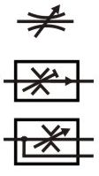
Flow control valves restrict the fluid flow and therefore actuator speed
Hydraulic systems generally use a flow restrictor to brake the movement of the load. A small orifice or restrictor valve is used to throttle the fluid flow and therefore control the actuator speed.
It may be useful to compare hydraulic control with a motor car, where either the engine throttle or brake pedal can control the speed, but the brake is considerably smaller and cheaper for the same power capacity. It is similar with hydraulics components, the pumps tend to be larger, more expensive and less robust than control valves, so generally, it's preferable and safer to brake the load with a valve rather than control its speed with a pump.
Also, lots of low-cost flow control valves can be used to control lots of actuators, all from one single power source.
Poppet check valves
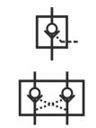
Poppet valves only allow flow in one direction and are used to restrict actuator creep.
Modern, high-quality hydraulic valves have very tight tolerances. But spool clearances provide small holes that allows fluid to leak through and therefore let the actuators creep while systems should be stationary.
Some valves use poppets instead of spools. Poppets generally have very low to practically zero leakage so they can be used to seal the flow and hold actuators in position for longer periods. The symbols shown here are of pilot operated check valves. These allow free flow in one direction but require and external pilot pressure to open the valve and allow flow in the other direction.
Example of why hydraulics is used
A major benefit of hydraulic fluid power systems is that the power source can be located remotely from where the power output is required. For example, on a large mobile excavator it may be easier to have a cooling fan driven directly from the engine drive shaft, however, this limits the fan location and blade clearance required to compensate for engine vibration. The small loss in system efficiency from using a hydraulic fan drive is more than compensated for by the increase in overall cooling efficiency. There is rarely space for an electric motor to drive the fan.