Self-study lesson plans and training record download page.
Hydraulic Pressure Transducer Measurements
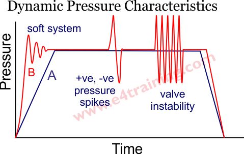
This figure shows a range of issues you may see in a hydraulic pressure against time signal. Curve A is an ideal system with the perfect performance curve you should want to see. Curve B exhibits several undesirable issues that you'd want to find and remove the cause for.
At the start of curve B, we see a typical damped, pressure ripple decay. It's likely this is due to the compliance within the hydraulic fluid. If you measure the time for one complete ripple and calculate the equivalent natural frequency then this will correlate with calculated system natural frequency, if system softness or compliance is the issue. Use our cylinder and valve system design guide to calculate the natural frequency of your system if you see this decaying pressure signal.
In the middle of curve B we see a sharp +ve and -ve pressure spike. These may occur on their own or together and indicate a shock load being applied to a hydraulic system. This may be a front loader bucket for example, as the vehicle reverses over a bump and the bucket bangs on the floor. Whatever causes these peaks, the high pressures can easily exceed the design pressure limits of the equipment and lead to early fatigue failures. Negative pressures can also be very serious, sucking in seals or causing cavitation, pitting damage.
The final oscillations on curve B are likely to be caused by resonance of a pressure control valve and will probably be clearly audible. Again this can easily exceed design pressure limits, damage valve seats or reach the million cycle, valve design life, very quickly. The likely cause of this instability is air pockets within the fluid although it can just be a system interaction issues for which changing the valve model, manufacturer or style is the only option.
Flow vs Pressure Measurement
Measuring the flow in a system may not be easy. Try to accurately record the cylinder times if possible although this often only checks the flow control valve setting, rather than the condition of the hydraulic pump.
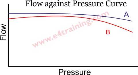
Loss of flow with increasing pressure is likely to be the first sign that the pump or actuator is failing and needs to be replaced. Different types of pump will have significantly different flow vs pressure characteristics and it may be worthwhile checking their performance across the range of speeds and temperatures, applicable to your system.
In our diagram curve A shows a pump with a much better flow vs pressure characteristic than the pump in curve B.
Pump performance can potentially be tested by installing a flow meter behind the loading valves, as shown in our instrumentation circuit example. However, if you use the safety relief valve as a loading valve you will need an additional safety relief elsewhere in the circuit.
Flow Testing at the Actuator
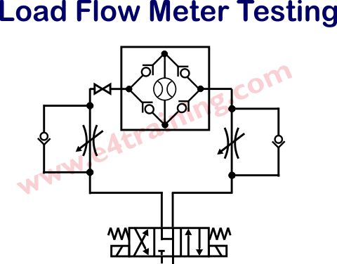
To check the flow available at an actuator it may be possible to replace the motor or cylinder with a flow meter in the middle of a Wheatstone bridge circuit, complete with manual loading valve. This arrangement could potentially be used to set up the flow control valves before the load is available, or as a replacement during commissioning.