Self-study lesson plans and training record download page.
Tips for operating and maintaining
All elastomers are slightly permeable to gasses and therefore bladder and diaphragm membranes will, over time, lose some gas pressure from the nitrogen into the hydraulic fluid. This leakage will depend on the application, temperature and the rubber used but maintenance engineers should check the gas pressure regularly and it's likely that a recharge will be required every 3 to 6 months. Note that the membrane permeability and damage can significantly increase in applications over 60C. Piston accumulators have no rubber bladder so are less likely to require regular recharges but dynamic seal movements and the risk of contamination damage to the seal mean that some pressure loss is possible.
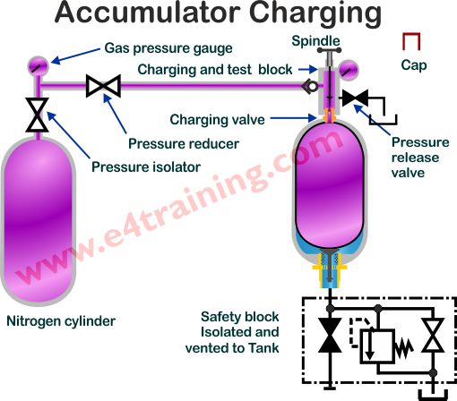 How to recharge an accumulator
Pre-charge pressures are likely to be 90% of the maximum working pressure for energy storage applications but always check the relevant drawings and/or maintenance instructions.
The actual gas pressure will vary with temperature changes so if you are recharging in particularly high or low ambient temperatures, or have a particularly critical application, it's worth using an appropriate pressure vs temperature chart before you start. This conversion will give you the correct pre-charge pressure for the ambient temperature on that particular day.
1. Check the specific manufacturer charging instructions for your equipment and application as they may vary from this general procedure.
2. Check the maintenance records to see when the last re-charge had taken place to make sure there are no signs of increased leakage or other potential failures.
3. Check the charging kit components are in good condition and the check the date of manufacture of the hose is within its expected working life. Also, check the gauges are within their calibration period.
4. Ensure the system power supply is turned off, isolated and tagged out. Isolate and vent the accumulator safely block before starting any work.
5. Remove the accumulator charging valve dust cap.
6. Make sure the spindle in the charging and test block is fully backed off and then attach it to the charging valve. The spindle is probably operated by an Allen key.
7. Close the pressure release valve in the charging block.
8. Install the connecting hose between the nitrogen cylinder and accumulator charging block.
9. With the reducing valves shut, very slowly open the nitrogen cylinder isolating valve and observe the internal pressure on the pressure gauge.
10. Very slowly screw the spindle down on the accumulator charging block until the gauge reads the pressure inside of the accumulator. Do not screw the spindle valve down as far as it will go.
11. Verify that the pressure in the nitrogen cylinder is higher than that of the accumulator and sufficient to charge the accumulator to the appropriate pre-charge pressure.
12. Very slowly open the reducing valve and observe the pressure increase on the accumulator charging block gauge.
13. Shut the nitrogen bottle isolator when the correct pressure is reached in the accumulator.
14. Allow the pressure inside the accumulator to settle for several minutes and carefully vent off through the release valve or repeat the charging procedure as required.
15. Release the spindle valves and slowly unscrew the pressure release valve to discharge the pressure inside the charging block and hose assembly.
16. Refit the dust cap and clean and replace the charging kit in its sealed container.
17. Complete the maintenance record for
Be very careful to only increase the pressure very slowly when charging accumulators. If nitrogen is allowed to expand rapidly it will decrease in temperature which can embrittle the bladder membrane leading to early failure. The bladder may also get stuck under the poppet.
Storage temperatures can also affect bladder life, whether installed or as a replacement part. Spare bladders must be stored away from UV light with some manufacturers specifying a maximum of only one-year storage.
Design features and operating characteristics
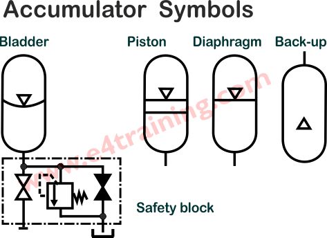
Bladder accumulators provide good contamination resistance and fast, dynamic response times. Their drawback can be the limited life of the bladder and the performance is compromised if the accumulator is placed on its side as the bladder may not hold its optimum shape.
Piston accumulators are more sensitive to contamination and rapid cycle failures due to their dynamic seal. They are available in a larger range of size and can utilise higher pressure ratios, therefore achieving a greater efficiency and range of volume changes. They can also be used in combination with nitrogen backup bottle which provides the possibility of significantly increasing the flow volumes they can supply.
The piston mass and elastomeric seal with its inherent hysteresis will reduce the dynamic performance compared to a bladder accumulator, however, this will still be very fast and appropriate for many applications.
Diaphragm accumulators have most of the advantages of bladder accumulators but are only available in a limited range of small sizes and it's generally not possible to change the rubber diaphragm.
How to specify hydraulic accumulators
The risk from accumulator failure is likely to be the first selection decision. The risk of a drop in performance is lower with a well-maintained bladder accumulator than a piston accumulator, because it does not have a sliding rubber seal that can easily be damaged by contamination or duty. The risk of sudden, complete failure is, however, much lower with the piston as a damaged seal is only likely to leak a limited amount of gas compared to the rubber bladder which may easily split once compromised.
Hydraulic accumulators are specified based on their volume change requirements and failure modes. Dynamic performance may also be critical in which case users are more likely to select a bladder or diaphragm accumulator.
Accumulators are most effectively sized by using one or more of the wide range of accumulator calculators available. The e4training accumulator calculator can be found here. There should also be a calculator specific to each product manufacturer but be aware that most versions have some approximations for temperature or adiabatic index, although for most applications the differences are not significant.
For larger systems with complex cylinder movements and timing, it's common to build a spreadsheet containing every movement and predicting the accumulator volumes that will be required. We will be adding one to the e4training.com calculator suit or download facilities soon.
Never install bladder accumulators on their sides e.g. horizontal.
This datasheet provides additional in formation on selecting an accumulator.
Design Tips, techniques and potential issues
Check your calculation carefully. Use different calculators to confirm the results and explore the extremes of operation to make sure there will be sufficient performance under all conditions. For example, try the calculations under isothermal and adiabatic conditions (n=1, n=1.4), consider high internal leakage losses based on 'end of life' or extreme temperature operation.
For transportation, it's recommended that bladder accumulators are pre-charged to around 2 bar (29psi). This helps to protect the bladder from damage. It is not recommended to deliver accumulators when fully charged and may require special licenses in some countries.